56
E-119TRI+DISC 345A / 345B: ASSEMBLY GUIDE
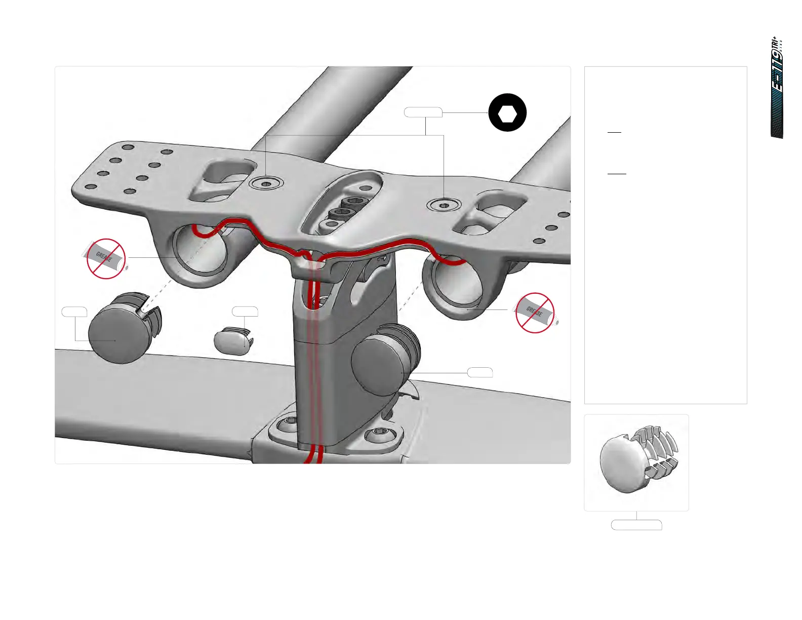
14.5.4 Cockpit assembly - routing - electronic cables
1. Reposition the extensions into the
bridge, making sure the surfaces
are free of grease.
Route the cables:
Di2
Run the Di2 cables through
the extensions.
Etap
Install the shifter onto
the extension.
Run the cables into the bridge
hole and down the spacer.
2. Connect the cables to the blipbox.
3. Clip the cables in the grooves
and push the excess into the
extensions.
4. Rotate the extensions to the
desired angle.
5. Install the extension caps (SKU:
81522). Choose the correct groove
to match the bridge angle.
6. Tighten the extension fixing
screws to 4 Nm.
7. Install the bridge plug
(SKU: 81521).
81521
4
6Nm
2.5
1Nm
4
5.5Nm
4
7Nm
2
HT-1/4
5
12Nm
2
2Nm
3
3Nm
4
3Nm
8
35Nm
2.5
HT
3
HT
40Nm
4Nm
T25
T25
4
3Nm
10
HT
2.5
5
9Nm
2.5
HT-2
2.5
HT-5
2.5
2Nm
3
2.5
HTHT
3
4Nm
M5 x 14mm
81522
81522
81522