TECHNICAL AREA
/ 46
2. 8 RESET MENU’ 2
2. 8. 0 Reset Factory Settings Reset OK = yes
ESC = no
To reset all default parameter settings, press the
OK button
2. 11 BOILER SETTINGS
2. 11. 0 Gas start offset adj from 0 to 30 9
2. 11. 1 Gas Control Offset from 0 to 190 88
2. 11. 2 Flue Duct Adj from 0 to 20 (%) 0
2. 11. 3 Enable standby
calibration
0 = OFF
1 = ON
1
2. 11. 4 Enable calibration CH
switch
0 = OFF
1 = ON
0
2. 11. 5 Enable DHW
calibrataion threshold
temperature
0 = OFF
1 = ON
1
2. 11. 6 DHW ignition threshold from 0 to 5 (°C) 0
2. 12 ADVANCED SETTINGS 2
2. 12. 1 Max DHW adjustable
from 0 to 100 (%)
100
4 ZONE 1 PARAMETERS
4. 0 SETPOINT
4. 0. 2 T set Zone 1 from 35 to 82 (°C)
(high temperature)
70
from 20 to 45 (°C)
(low temperature)
25
To set only with Fixed Flow Temperaure (see
421)
4. 2 ZONE 1 SETTINGS
4. 2. 0 Zone 1 Temperature
range
0 = from 20 to
45°C
(low temperature)
1 = from 35 to 82°C
(high temperature)
1
4. 2. 1 Thermoregulation
To enabled
thermoregulation press
Auto button.
On the dispaly will
appear the symbol
AUTO
0 = Fixed Flow
Temperature
1 = Basic
Thermoregulation
2 = Room Temp
only
3 = Outdoor Temp.
only
4 = Room +
outdoor
Temp.
1
menu
sub-menu
parameter
description value
default
setings
menu
sub-menu
parameter
description value
default
setings
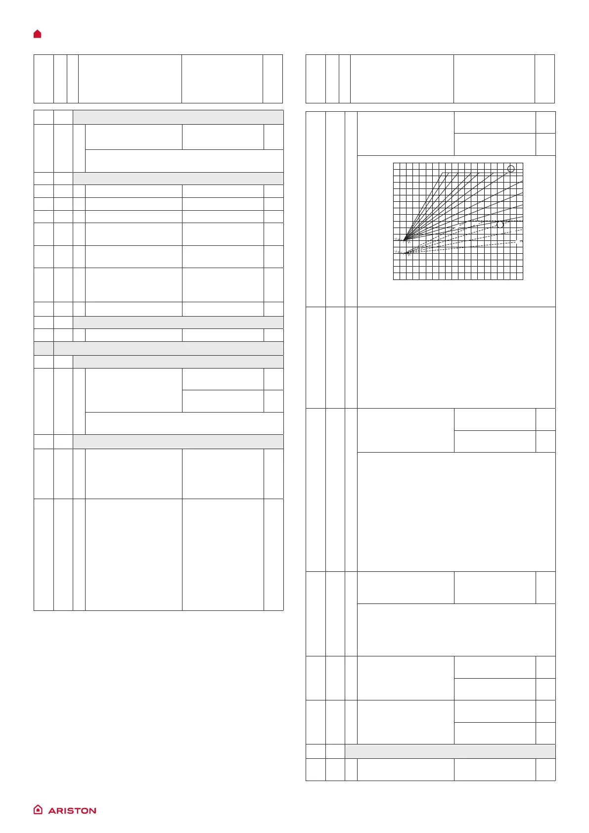
4. 2. 2 Slope from 1.0 to 3.5
(high temperature)
1.3
from 0.2 to 1.0
(low temperature)
0.6
°C
°C
Flow Temperature
Low temperature High temperature
External temperature
Ambiente temperature
setting value
23
23
21
21
19
19
30
20
10
0
40
50
60
70
80
90
°C
510152025
3.5
3.0
2.5
2.0
1.8
1.5
1.3
0.8
1.0
0.6
0.4
0 -5 -10 -15 -20 -25 °C
0.8
0.6
1.0
0.4
0.2
When an outdoor sensor is used, the boiler
calculates the most suitable delivery
temperature, taking into account the outside
temperature and type of system.
The type of curve should be selected in
correspondence with the projected temperature
of the system and the nature of the dispersions
present in the structure.
For high-temperature systems, one of the curves
depicted below may be chosen.
4.
2. 3 Offset
Auto Function active
from - 14 to + 14 (°C)
(high temperature)
0
from - 7 to + 7 (°C)
(low temperature)
0
To adapt the heating curve to the system
requirements, shift the curve in parallel so that
the calculated ow temperature is modied, in
addition to the room temperature.
By accessing the parameter and pressing the
button b, it is possible to shift the curve in a
parallel direction. The shifting value can be read
on the display: from -14 to +14 for high-temperature
devices, or from -7 to 7 for low-temperature
devices. Each step corresponds to a 1°C increase/
decrease In the ow temperature with respect to
the set-point value.
4. 2. 4 Room Inuence
Proportional
Auto Function active
from 0 to 20 20
If setted = 0 the room temperature doesn’t
inuence the calculation of the set-point.
If setted = 20, the room temperature has the
maximun inuence to calculate the set-point
- only active when the BUS device is connected
4. 2. 5 Maximum CH
Temperature Zone 1
from 35 to 82 °C
(Param. 420 = 1)
82
from 20 to 45 °C
(Param. 420 = 0)
45
4. 2. 6 Minimum CH
Temperature Zone 1
from 35 to 82 °C
(Param. 420 = 1)
35
from 20 to 45 °C
(Param. 420 = 0)
20
4. 3 Z1 DIAGNOSTICS
4. 3. 4 Heat request Zone 1 0 = OFF
1 = ON

 Loading...