INSTALLATION
/ 20
Connecting the Flue
Flue System
The provision for satisfactory ue termination must be made as described in BS 5440-1:2008.
The appliance must be installed so that the ue terminal is exposed to outdoor air.
The terminal must not discharge into another room or space such as an outhouse or lean-to.
It is important that the position of the terminal allows a free passage of air across it at all times.
The terminal should be located with due regard for the damage or discolouration that might occur on buildings in the vicinity, it must
also be located in a place not likely to cause nuisance.
In cold or humid weather water vapour may condense on leaving the ue terminal.
The effect of such “steaming” must be considered.
If the terminal is less than 2 metres above a balcony, above ground or above a at roof to which people have access, then a suitable
stainless steel terminal guard must be tted.
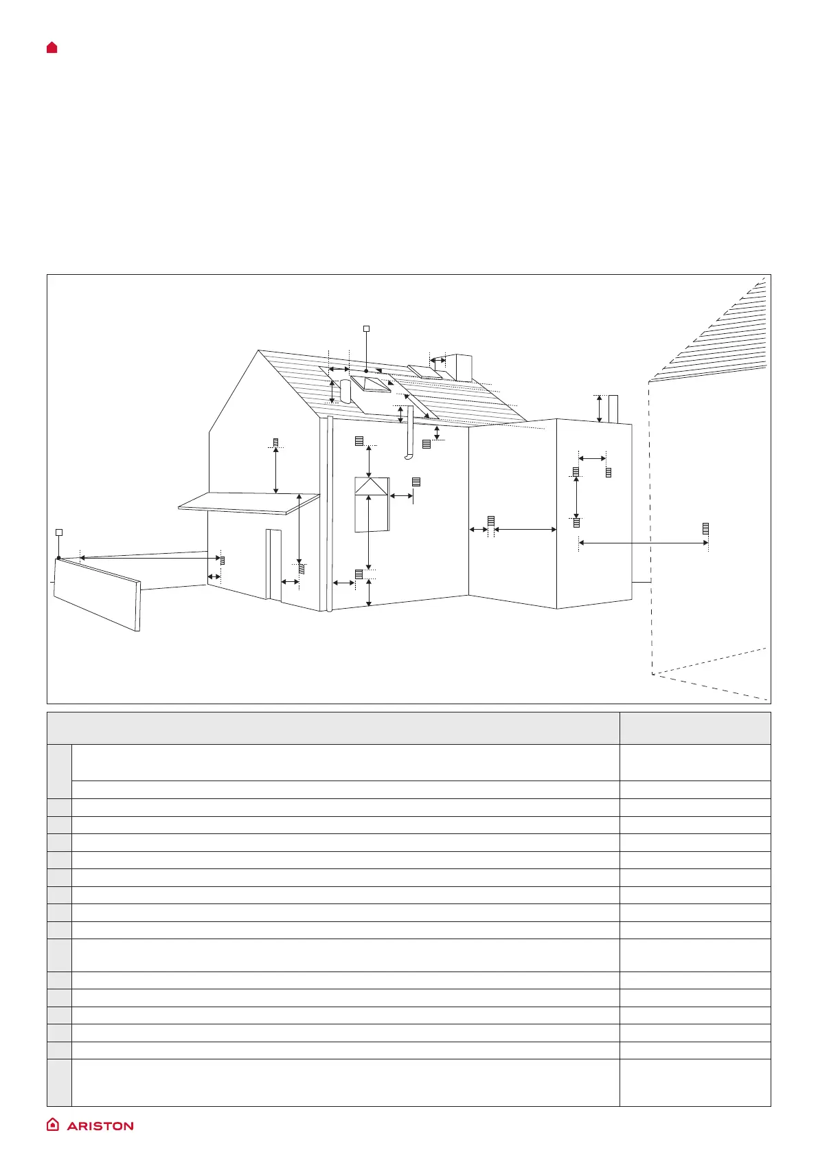
The minimum acceptable spacing from the terminal to obstructions and ventilation openings are specied in Fig. 1.
Fig. 1
H H
A
G
C
B
I
I
F
H
L
J
boundary
flues should not
penetrate this area
N
Q
2000mm
600mm
600mm
M
K
D, E
Q
Q
P
Location Fanned
draught
A Below an opening
300
B Above an opening 300
C Horizontally to an opening 300
D Below gutters, soil pipes or drain pipes 75
E Below eaves 200
F Below balcony or cart port roof 200
G From a vertcaldrainpipe or soil pipe 150
H From an internal or external corner, or to a boundary alongside the terminal 300
I Above ground, roof or balcony level 300
J From a surface or a boundary facing
the terminal
600
K From a terminal facing the terminal 1200
L From an opening in the car port into the building 1200
M Vertically from a terminal on the same wall 1500
N Horizontally from a terminal on the same wall 300
P From a structure on the roof N/A
Q Above the highest point of intersection with the roof Site in accordance
with manufacturer’s
instructions

 Loading...