35 / IT
MENU
SOTTO-MENU
PARAMETRO
DESCRIZIONE RANGE
IMPOSTAZIONE
DI FABBRICA
0 RETE
0 2 Rete BUS
0 2 0 Rete BUS attuale
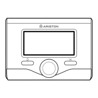
Interfaccia di sistema
Energy Manager
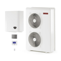
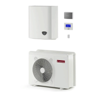
Pompa di calore
Sensore ambiente
Controllo multi zona
0 3 Interfaccia di sistema
0 3 0 Numero zona
Nessuna zona selezionata
Zona selezionata
0
0 3 1 Correzione temperatura ambiente - 3; +3 0
0 3 2 Versione SW interfaccia
4 PARAMETRI ZONA 1
4 0 Impostazione Temperature
4 0 0 Temperatura Giorno 10 - 30 °C 19°C Heat - 24°C Cool
4 0 1 Temperatura Notte 10 - 30 °C
13°C
4 0 2 Temperatura set Z1 par. 4.2.5 - 4.2.6
20°C (LT) - 40°C (HT)
4 0 3 Temperatura antigelo zona 2 - 15 °C
5°C
4 1 Funzione estate/inverno automatico
4 1 0 Attivazione estate/inverno auto OFF - ON OFF
4 1 1 Limite temp. estate/inverno auto 10 - 30 °C 20°C
4 1 2 Ritardo commut. estate/inverno [0-600] 300 min
4 2 Impostaz Zona1
4 2 0 Range Temperatura
Bassa Temperatura
Alta Temperatura
Alta Temperatura
4 2 1 Selezione Tipologia Termoregolazione
Temperatura Fissa di Mandata
Dispositivi ON/OFF
Solo Sonda Ambiente
Solo Sonda Esterna
Sonda Ambiente + Sonda Esterna
Dispositivi ON/OFF
4 2 2 Curva Termoregolazione 0,2 - 1 (LT); 1 - 3,5 (HT)
0,6 (LT) - 1,5 (HT)
4 2 3 Spostamento Parallelo -14 ÷ +14 (HT); -7 ÷ +7 (LT)
0°C
4 2 4 Inuenza Ambiente Proporzionale 0 - 20°C
2°C (LT) - 10°C (HT)
4 2 5 Max T 20°C ÷ 45°C (LT); 20°C ÷ 70°C (HT)
45°C (LT) - 60°C (HT)
4 2 6 Min T 20°C ÷ 45°C (LT); 20°C ÷ 70°C (HT)
20°C (LT) - 20°C (HT)
4 2 9 Modalità richiesta calore
Standard
RT Time Programs Exclusion
Forzamento richiesta calore
Standard
4 3 Diagnostica Zona1
4 3 0 Temperatura Ambiente
sola lettura
4 3 1 Temperatura Set ambiente
sola lettura
4 3 2 Temperatura mandata
sola lettura
4 3 3 Temperatura ritorno
sola lettura
4 3 4 Stato Richiesta Calore Z1 OFF - ON
sola lettura
4 3 5 Stato Pompa OFF - ON
sola lettura
4 4 Dispositivi Zona1
4 4 0 Modulazione pompa zona
Velocità ssa
Modulante su deltaT
Modulante su pressione
Modulante su deltaT
4 4 1 DeltaT obbiettivo per modulazione 4 ÷ 25°C
7°C (LT) - 20°C (HT)
4 4 2 Velocità ssa pompa 20 ÷ 100%
100%
 Loading...