EasyManua.ls Logo

Ariston NIMBUS PLUS S NET User Manual

Ariston NIMBUS PLUS S NET
96 pages
Go to English
To Next Page IconTo Next Page
Page #1 background imageLoading...
Page #1 background image
IT
NIMBUS PLUS S NET
ISTRUZIONI TECNICHE PER L’INSTALLAZIONE E LA MANUTENZIONE
TECHNICAL INSTRUCTIONS FOR INSTALLATION AND MAINTENANCE
OK
420000400404
3300828
3300829
3300830

Table of Contents

Question and Answer IconNeed help?

Do you have a question about the Ariston NIMBUS PLUS S NET and is the answer not in the manual?

Ariston NIMBUS PLUS S NET Specifications

General IconGeneral
TypeAir-to-water heat pump
RefrigerantR32
Energy Efficiency Class (Heating)A++
Energy Efficiency Class (Cooling)A++
Maximum Flow Temperature60°C
Weight (Indoor Unit)45 kg
ConnectivityWi-Fi
Dimensions (Outdoor Unit)950 mm

Summary

Maintenance

Internal Unit Error List

Internal Unit Error List (Continued)

Error codes and troubleshooting

Continuation of internal unit errors and solutions.

External Unit Error List

Error codes and reset procedures

List of external unit error codes and reset methods.

Inverter error codes and troubleshooting

Troubleshooting for external unit inverter errors.

Inverter Error List

Inverter error codes

Detailed list of inverter error codes for troubleshooting.

ODU inverter error codes

Detailed list of ODU inverter error codes.

Inverter Error List (ODU Specific)

Safety Regulations

Key to symbols

Explanation of symbols used to denote risks and warnings.

General safety warnings

General safety advice for installation and handling.

Safety Regulations (Continued)

Continued safety precautions

Further safety advice for operation and maintenance.

Installation Guide

Pre-installation considerations

Important considerations before appliance installation.

External Unit Installation

Internal Unit Installation

Gas Connections

Safety and connection procedure

Safety notes and steps for connecting gas pipes.

Air purging and refrigerant charging

Procedures for air purging and refrigerant charging.

Electrical Wiring

Safety and circuit requirements

Safety notes and electrical circuit requirements.

External unit connection table

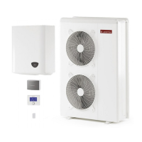
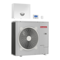
Electrical connection details for external units.

Internal Unit Electrical Connections

Electrical supply and connection details

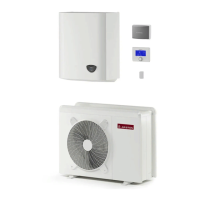
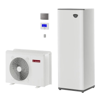
Electrical supply and connection details for internal units.

External Unit Electrical Connection

Internal Unit Electrical Connection

Connection procedures and warnings

Connecting power/control signals and thermostat advice.

Inter-unit Electrical Connections

Terminal connections and notes

Connecting terminals and surge protection recommendations.

Electrical Scheme - External Unit

1 PH (4-5-7kW) diagram

Electrical diagram for 1-phase external units.

3 PH (7kW) diagram

Electrical diagram for 3-phase external units.

Electrical Scheme - External Unit (Continued)

3 PH (9-11kW) diagram

Electrical diagram for 3-phase external units.

1 PH (9-11kW) diagram

Electrical diagram for 1-phase external units.

Electrical Scheme - Internal Unit (WH 90 110 S)

Safety warnings

Safety warning regarding terminal access and plate removal.

Electrical Scheme - Internal Unit (WH 70 S)

Electrical Scheme - Internal Unit (WH 40 50 S)

Internal unit wiring diagram

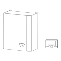
Wiring diagram for internal unit models WH 40 50 S.

Installation of System Interface

System Configuration

Commissioning procedure

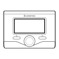
Steps for initial setup and language selection.

Technical Area Access

How to enter the technical area and access menus.

HP System Parameters

Cooling Parameters

Parameters for cooling operation.

Domestic Hot Water Parameters

Parameters for domestic hot water settings.

HP System Parameters (Continued)

Central Heating Parameters

Parameters for central heating operation.

DHW and Thermal Cleanse settings

Advanced DHW settings, boost, and thermal cleanse.

Thermoregulation

Zone 1 Parameter Access

Accessing and adjusting Zone 1 thermoregulation parameters.

Zone 1 Cooling Parameters

Zone2 Parameters (Continued)

HP System Parameters

Accessing and setting Heat Pump system parameters.

EM Input/Output Configuration

Configuration of Energy Manager inputs/outputs.

HP Diagnostics - 1

HP Diagnostics - 2

HP Diagnostics - 2 (Continued)

EM Diagnostics - 1 Input

EM Diagnostics - 1 Input (Continued)

EM Diagnostics - 2 Output

Reset Menu

Buffer Configuration

Related product manuals