Page 22 Installation manual for the CD72/95/15003
CONNECTION OF AN EXTRA POWER SUPPLY
An auxiliary power supply will be required if the voltage is too low as a result of large cable runs or the
current demand is in excess of the panels current supply rating.
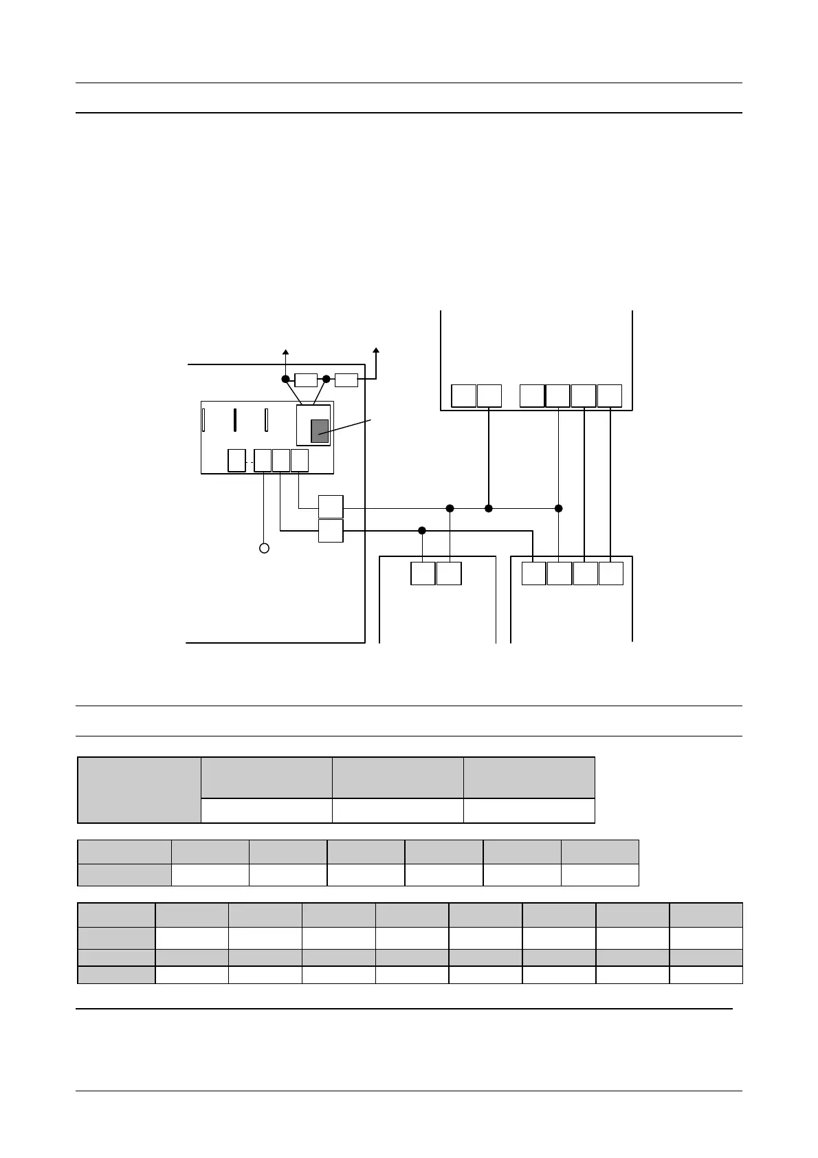
To connect an extra power supply the ‘+’ of the panel must not be connected to the ‘+’ of the auxiliary power
supply. Also do not connect the ‘+’ of different auxiliary power supplies together. If the auxiliary power
supply is used to power a remote expander/keypad, connect the “+” of the four wire bus (“A”) to the “+” of
the auxiliary power supply. A common reference is obtained by connecting together all power supplies “-”.
IMPORTANT: NEVER INTERCONNECT POSITIVES OF POWER SUPPLIES
ALWAYS INTERCONNECT NEGATIVES OF POWER SUPPLIES
A B C D-+
4-wire bus
Central
power
A B C D
4-wire bus of
keypad or
expander
D E
BU4
4K7 4K7
To “Power Monitor” zone
CD72/95/15003
Auxiliary power
supply PG822
-+
Detector,
siren, relay,
etc...
Detects failure of
the mains power
Figure 15. Use of an extra power supply
INPUTS
panel CD7203 panel
CD9503/15003
expander socket
CD9503/15003
Numbering
1....8 1....16 145....152
Keypad 1 Keypad 2 Keypad 3 Keypad 4 Expander 5 Expander 6
CD7203
9....12 13....16 17....20 21....24 9....16 17....24
Keypad 1 Remote 2 Remote 3 Remote 4 Remote 5 Remote 6 Remote 7 Remote 8
CD95/150
17....20 25....32 33....40 41....48 49....56 57....64 65....72 73....80
Remote 9 Remote10 Remote11 Remote12 Remote13 Remote14 Remote15 Remote16
CD95/150
81....88 89....96 97....104 105....112 113....120 121....128 129....136 137....144
Table 2. Numbering of the inputs
Note: In the CD7203 the expanders have priority over the keypads !