Page 8 Installation manual for CD72/95/15003
BEFORE SWITCHING ON THE POWER
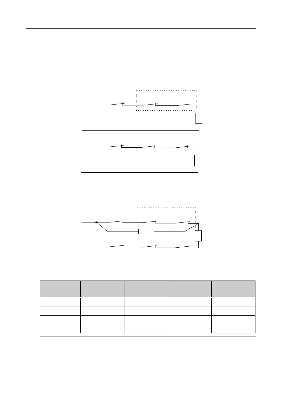
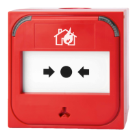
1. Detectors (or key switches) can be connected in two ways:
Conventional: One zone each is required for both tamper and the alarm. Both zones should be
closed with an end-loop resistor (4.7 kOhm). Program the ‘zones’ menu as
‘Alarm’
Zone input
Alarm
Alarm
Alarm
4K7
Zone input
Tamper
Tamper
Tamper
4K7
Figure 1. Separate alarm and tamper connection
Dual loop: The alarm and tamper are placed together in one zone. The zone has two end-loop
resistors (4.7 kOhm) to differentiate between alarm and tamper. Figure 2 shows how
they are connected. Program the ‘zones’ menu as ‘Dual’.
Zone input
Alarm
Alarm
Alarm
4K7
Tamper
Tamper
Tamper
4K7
Figure 2. Joint connection of the alarm & tamper
This connection method gives the following input values:
The zone is Resistance Panel zone
voltages
Remote zone
voltages
Reaction
on standby 3k5 - 6k2 2.1 - 2.8 V 4.7 - 6.8 V none
triggered 6k6 - 11k7 2.9 - 3.6 V 6.9 - 8.6 V alarm
open > 12k7 > 3.7 V > 8.7 V tamper
short-circuited < 2k9 < 1.9 V < 4.6 V tamper
Table 1. Operation of the inputs