Installation manual for the CD72/95/15003 Page 27
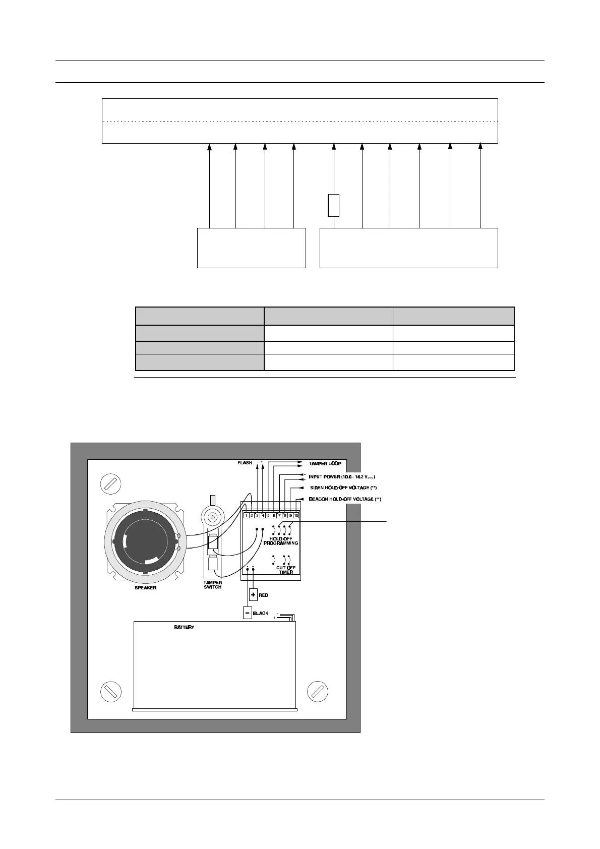
CONNECTION OF AN AS256 AND AS294/394 SOUNDER
32
33
11
52
10
51
Bc
30
33
31
34
13
8
57
12
53
39
39
4K7
CD7203
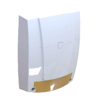
Figure 22. Connection of the AS294/394 + internal siren AS256
Programming CD7203 CD9503/15003
Beacon control
01 Int Sir Sy + 01 Int Sir Sy +
internal siren control
18 Int Sir Sy - 49 Int Sir Sy -
external siren control
19 Ext Sir Sy + 50 Ext Sir Sy +
Table 4. Programming for the sirens
NB: If the tampers must be placed in separate zones, they can be connected according to
figure 1 (1 end-loop resistor) or figure 2 (2 end-loop resistors) (see page 8).
Figure 23. Connection of the AS294/394
Cut these 2 jumpers for
negative Hold-Off.
The other 2 jumpers for
positive Hold-Off.