Installation manual for the CD72/95/15003 Page 25
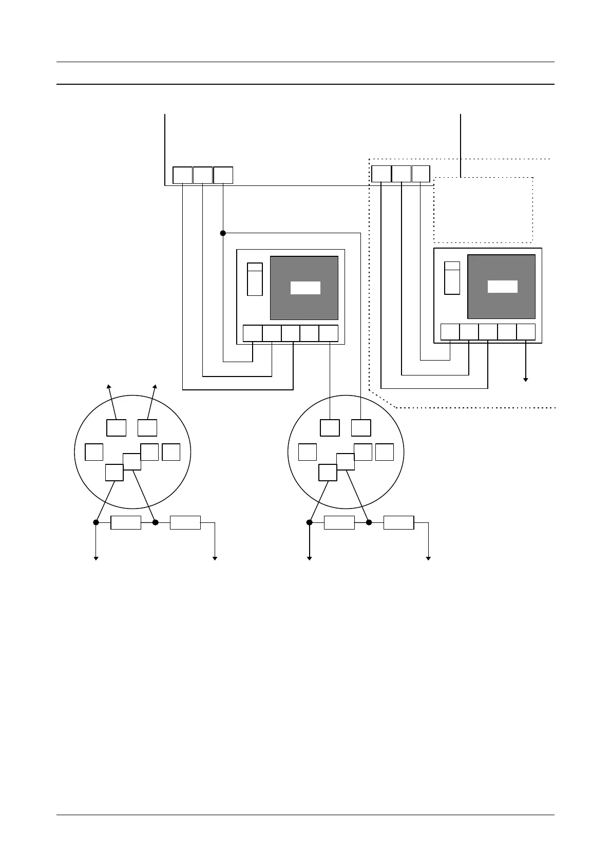
CONNECTION OF A FIRE DETECTOR
+O1-
1
5 2
16
NC
CD72/95/15003
DB822
+
DP803
NO
C
To “fire” zone
2 3 4 5
4 1
23
7
DB602
+
DP611/
DI612/
DT613
9
8
To “fire” zone
1 2 3 4 5
+O3O2
To siren
control (Sc)
This extra connection is
only necessary if a
continuous signal from
the external siren is
required
To terminal
“5” of the
RC213 relay.
To “+”
terminal of
the panel
O1 = “Fire reset -”
O2 = “External siren”
O3 = “Fire -”
Figure 20. Connection of a fire detector
Note 1: If there are several detectors place them in parallel and cable the zones as described in
figure 1 or 2 (see page 8).
Note 2: This connection also applied for detectors which require a reset after an alarm, e.g. the
GS900 etc.
Note 3: The reset is performed after the second entry of a code after an alarm.
Note 4: Programme zone loop as “Dual”.
Note 5: Programme all outputs for negative applied “-”.