9.45”
(240 mm)
4.53”
(115 mm)
ISO F05 (CPMA0071)
1.12” (28.5 mm)
0.4” x 0.4” (10 mm x 10 mm)
7.09” (180 mm)
27 lb (11.5 kg)
14.09” (358 mm)
13.31” (338 mm)
3.54” (90 mm)
18 lb (8 kg)
11.81” (300 mm)
11.02” (280 mm)
G12 G13
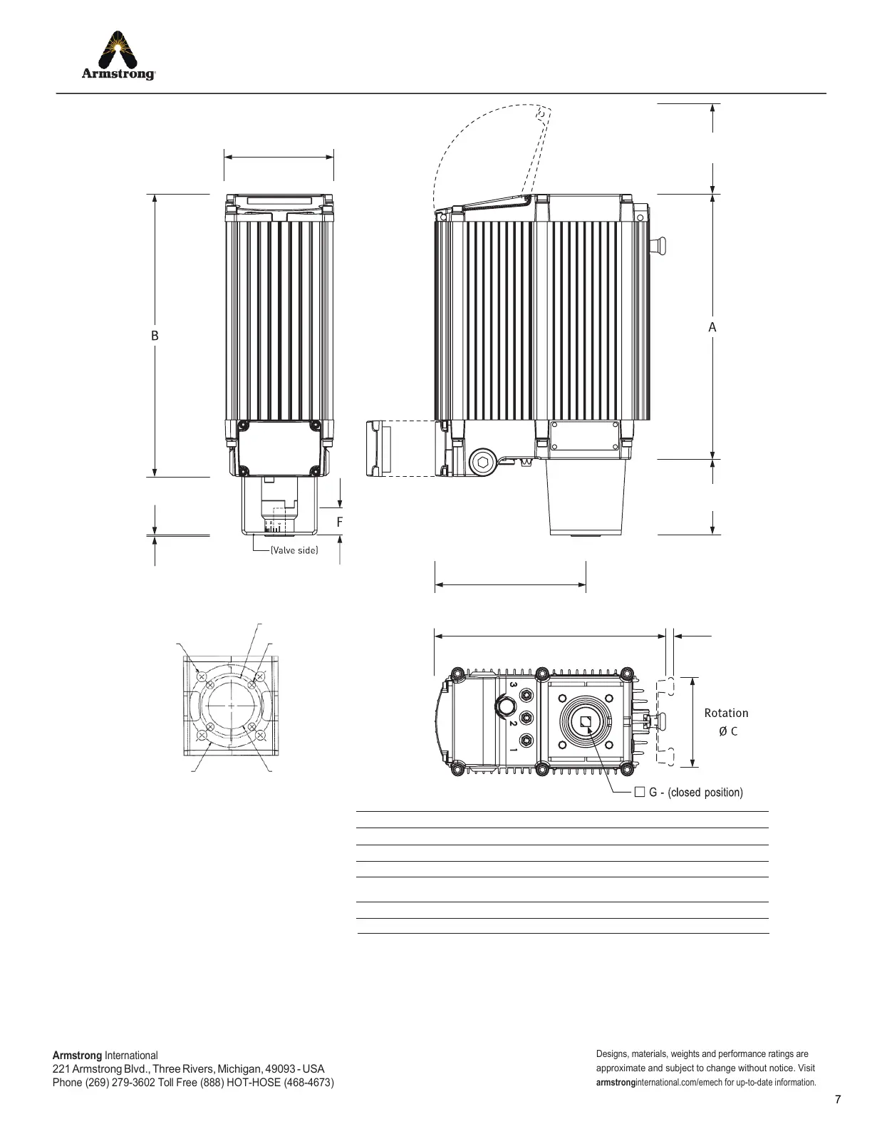
Mechanical Data
Height A
Height B
Weight
Rotation C Ø
F : Maximum shaft depth
G : Coupling (ID) square
Note: Actuator side of mounting kits are all F07. Other mounting kits are available on request.
ISO F07 (CPMA0070)
1.12” (28.5 mm)
0.55” x 0.55” (14 mm x 14 mm)
Mounting Bracket Detail
(valve side shown)
Allow access for wiring
screw terminal and cable entry
(see installation instructions)
Pull out handle
to engage
0.04”
(1 mm)
6.30”
(160 mm)
0.32”
(8 mm)
3.15”
(80 mm)
3.82”
(97 mm)
4 X Ø0.33”
(8.5 mm)
PCD 1.97”
(50 mm)
4 X Ø0.26”
(6.5 mm)
Ø1.53”
(93 mm)
PCD 2.76”
(70 mm)
Dimensions
Armstrong
International
221
Armstrong Blvd., Three Rivers, Michigan, 49093 - USA
Phone (269) 279-3602 Toll Free (888) HOT-HOSE (468-4673)
Designs, materials, weights and performance ratings are
approximate and subject to change without notice. Visit
armstrong
international.com/emech for up-to-date information.