paired and changed to green when synced (wireless communication between HRC and the lantern is
established) to the paired unit.
• A long, slow beep and red light on Status Indicator will indicate failed pairing.
The following issues may cause failed pairing:
1. USB cable is not attached properly
2. Unit is already paired on Unit2 (right side of the remote).
3. The eSTOP™ unit has no power/is not turned on (push green button at base of eSTOP™).
4. The HRC and Lantern units are not in test mode
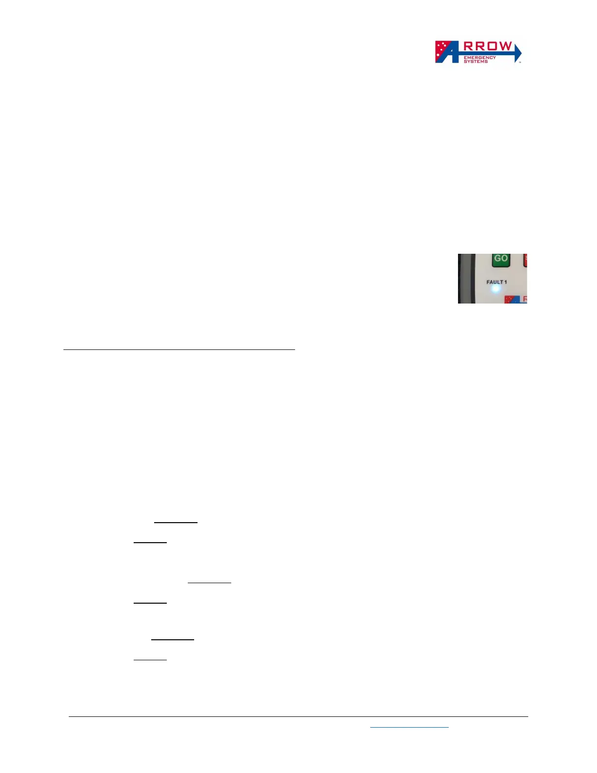
Once paired and synced (Fault1 indicator is Green, allow up to 60 seconds for this to turn Green), unplug
the USB cable, and a lantern LED test (short press unit1 “GO” button) can be performed to test the paired
lantern, follow HRC Operational Procedures to perform LED test and operate the lantern units.
For eSTOP™ Multi models only, a second lantern can be paired to Unit1 (same side
on the HRC), this is done by plugging the HRC to the second lantern and repeat the
same process above, using the same side GO Button. When 2 lanterns are paired to
Unit1 of the HRC, the lanterns are controlled simultaneously and behave identically.
And Fault indicators will indicate Cyan color instead of green, indicating 2 units is
paired. The same process can be done with HRC Unit2 GO button.
Pairing eSTOP™ HRC Unit2 (right side of the HRC)
1. Repeat the pairing process by pressing Unit2 GO button ❼ in Test Mode. Unit1 on the HRC
must be paired to an eSTOP™ before Unit2 can be paired.
Note: This is pairing a second lantern to right side of the same HRC. This pairing setup allows 2
lanterns to be controlled such that only 1 lantern can be Green at any time (Shuttle flow mode). If
pairing as single unit operations, only pair to Unit1 on each HRC with each eSTOP™. Unit2 on HRC
is not used for single unit operations.
Pairing for Application Scenarios
Shuttle Control → Required: 2 x eSTOP Lanterns, 1 x HRC
Pairing: 1 eSTOP Lantern to unit1 on HRC, 1 eSTOP Lantern to unit2 on HRC
Plant Crossing Control → Required: 2 x eSTOP Lanterns, 2 x HRC
Pairing: 1 eSTOP Lantern to unit1 on HRC1, 1 eSTOP Lantern to unit1 on HRC2
Gating Control → Required: 1 x eSTOP Lanterns, 1 x HRC
Pairing: 1 eSTOP Lantern to unit1 on HRC