9.3 Connectors on the telescope
9.4 Fork side A
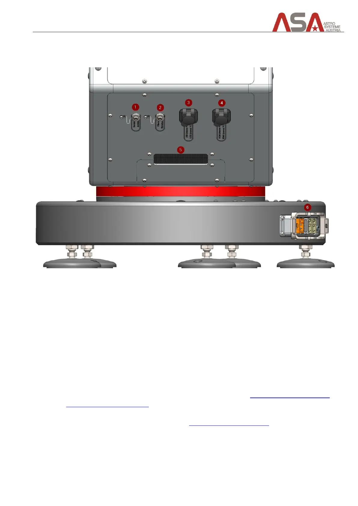
Figure 36 - Connectors on fork side A
1 Derotator (optional)
contains power and data connection
2 Filter wheel (optional)
contains power and data connection
3 USB
you can connect your camera/filter wheel here or you can connect a keyboard/mouse to access the
telescope control unit (TCU) for maintenance purposes
4 HDMI
you can connect a monitor here to gain access to the telescope control unit (TCU) – only for
maintenance purposes
5 In-/outlet for user cables
you can lay wires for your equipment through this hole (see chapter Connecting cables for camera
and other user specific devices)
6 Telescope base connector
connects telescope with cabinet (see chapter Telescope Electronics Cabinet)