Page 16 Version 2.14 Maintenance and Service Manual
8. Description of the PLC diagnostic system
The lift unit is fitted with an acoustic alarm signal which will be activated in case of a failure during operation.
The failure can be identified by the information on the display and the appropriate counter measures listed in
chapter 6 should be taken.
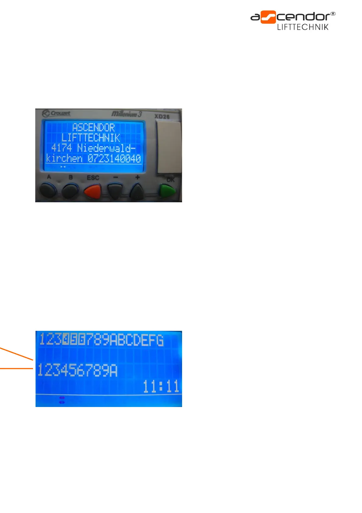
8.1 Normal condition
To enter the main menu please press UP and DOWN button simultaneously for at least 5 seconds, or press the
A and B button simultaneously for at least 3 seconds.
For navigation in the main menu press the A or B button.
Choose your settings with + and – on the particular menu site.
Press ESC to leave the main menu.
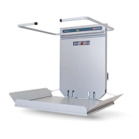
8.2 Input-Output status of the PLC
After you have opened the main menu the Input-Output picture appears.
This is very useful for failure search.
In the course of trouble shooting with Ascendor telephone support you may be asked to handover this
information.
(I = Input, O = Output)
Input = top line
Output = bottom line
In this example the inputs 4, 5, and 6 (dark coloured numbers and letters) are activated.
This means that the lift is located in the lower stop and the platform is opened.
I-4 = limit switch BOTTOM (b4)
I-5 = platform switch (b20)
I-6 = emergency stop circuit (b13, b15)