Page 26 Version 2.14 Maintenance and Service Manual
12.5 Removing the safety bar motors
For PLG7 units: remove the rear plastic cover and remove the radio receiver.
For PLK8 units: remove the front plastic cover (see chapter 3) and remove the radio receiver.
Ensure that the safety bars are in the horizontal position.
Disconnect the electrical supply from the motor.
Loosen the slip clutch and remove the two 5mm Allen key screws and remove the motor from the rear side.
12.6 Removing the PLG7 limit switches
The lift must be positioned at the lower station.
Remove the front plastic cover (see chapter 3).
Remove on the main printed circuit board the
cable for the limit switches (terminal block X2,
terminal A to H).
Secure the lift to the front with a safety strap.
Fold the main printed circuit board away to the
left.
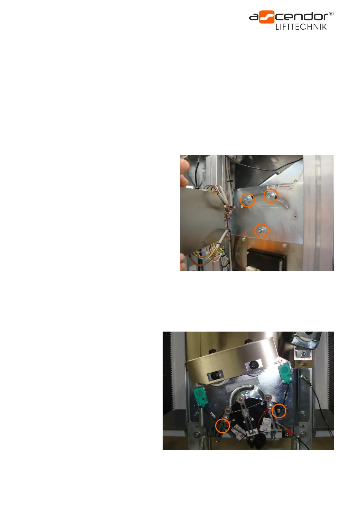
Remove the 3 lock nuts (wrench size 17mm) which
are located behind the main circuit board.
(Lifts with a steep rail have 4 lock nuts)
Tilt the lift slightly forwards and remove the swivel plate with the switches by pulling it away from underneath.
12.7 Removing the PLK8 limit switches
The lift must be positioned at the lower
station.
Remove the front plastic cover
(see chapter 3).
Remove on the main printed circuit board
the cable for the limit switches
(terminal block X2, terminal A to H).
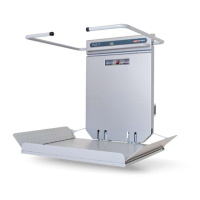
Remove the two hexagon bolts
(wrench size 10mm) and take the plastic
block with the switches away from
underneath.