Page 10 Version 2.14 Maintenance and Service Manual
5. Position and function of the switches b1 to b28
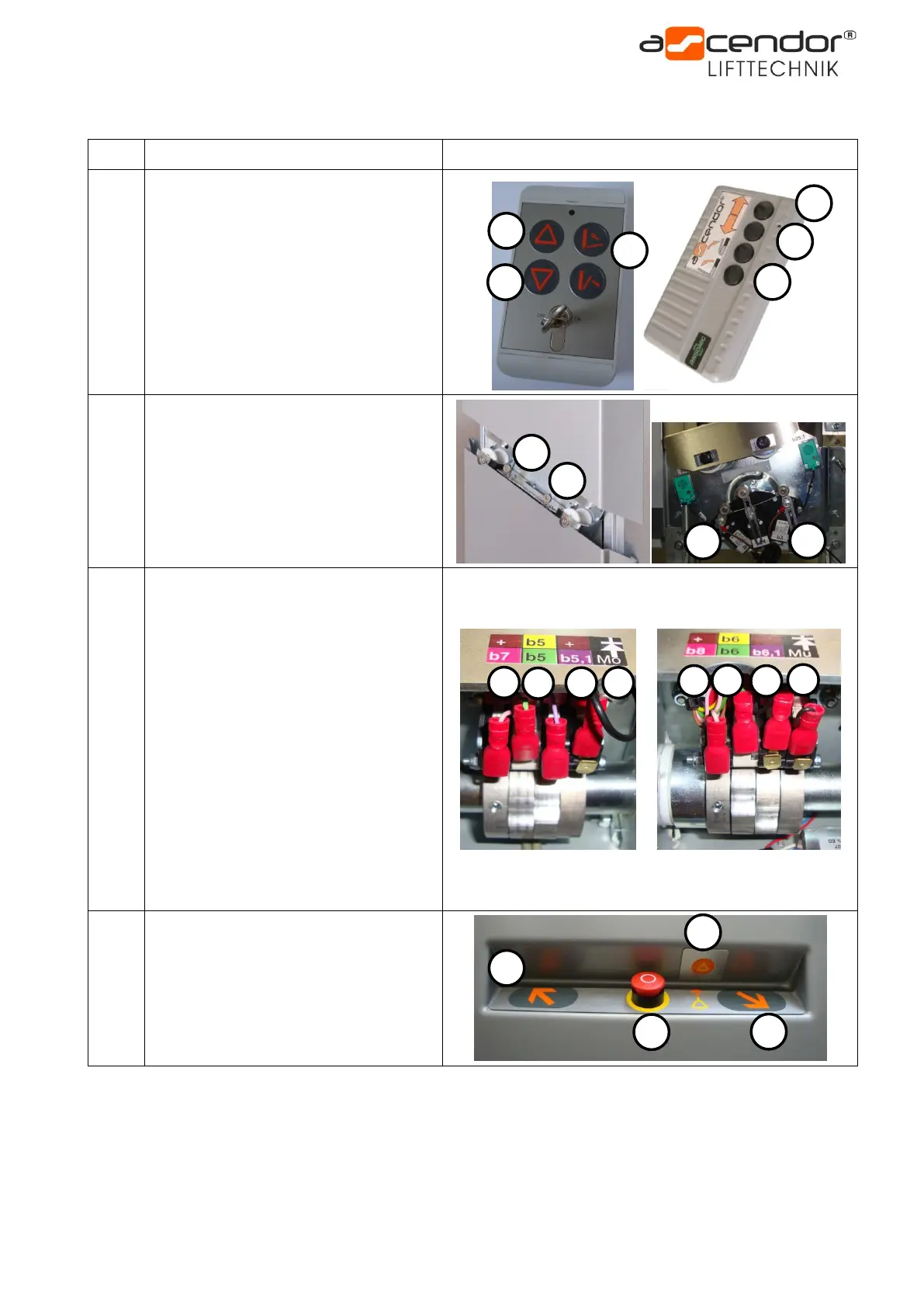
wireless remote controls
1 – UP button
2 – DOWN button
3 – folding
1 – limit switch top PLG7
2 – limit switch bottom PLG7
3 – limit switch top PLK8
4 – limit switch bottom PLK8
Positioned on the back side of the lift at
PLG7 and PLK8 units
b5
b5.1
b6
b6.1
b7
b8
b9
b10
1 – safety bar switch top / middle
position
2 – safety bar switch top / middle PLC
3 – safety bar switch bottom / middle
position
4 – safety bar safety switch
5 – safety bar switch top / down
position
6 – safety bar switch bottom / down
position
7 – safety bar switch top / high position
8 – safety bar switch bottom / high
position
Positioned behind the front plastic
cover on the upper component
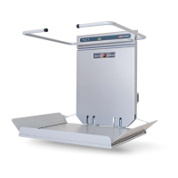
1 – UP button internal control
2 – DOWN button internal control
3 – emergency stop button
4 – emergency call button