TD 92679EN
22 November 2013 / Ver. G
Installation Guide
Elise3
10
4. Installation and Configuration
4. Installation and Configuration
The Elise3 can be mounted vertically on a wall or be placed horizontally in a 19” rack. It must
be fixed by screws or other fixtures to the wall or rack, and must not be easily movable.
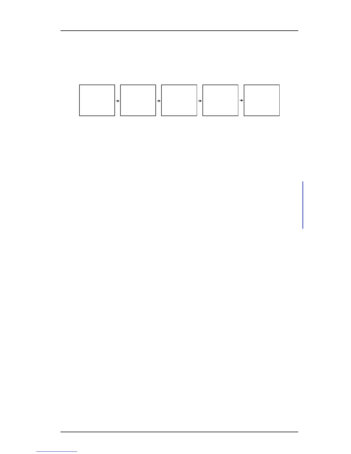
Figure 5. Recommended installatio
n and configuration procedure
Connect the
supply voltage
Access the
application
Mount the
hardware
Basic
configuration
Connect
to required
equipment
4.1 Mounting
4.1.1 Environmental
The Elise3 shall be placed in an environment with an am
bient temperature between 0°C to
+40°C (32°F to 104°F). Relative humidity: 30 - 85% RH (non condensing).
4.1.2 Installations Requiring Seismetic Considerations
When installing the Elise3 in geographic
regions with seismic conditions and special
considerations, check regional codes and regulations to determine if any requirements exist
and apply for securely mounting ITE equipment.
After the desired rack or cabinet is installed, install the Elise3 in accordance with the
instructions in 4.1.3 Wall Mounting and 4.1.4 Rack Mounting on page 11.
4.1.3 Wall Mounting
Four screws size 3.5×40 mm (0.14×1.6 in) togethe
r with four wall plugs and four screws
size M3×6 mm (0.12×0.24 in), are delivered with the product. The M3×6 screws are used
for attaching the assembly brackets to the module. Use the 3.5×40 mm (0.14×1.6 in)
screws for walls made of wood. For walls made of concrete and bricks use them together
with the wall plugs. For other types of walls use suitable screws and plugs according to wall
material.
IMPORTANT: When mounted on a wall, it is of great
importance that the connections are
located in a vertical plane.
1 Fasten the supplied assembly brackets on the
bottom side of the Elise3.
2 Use the supplied screws and wall plugs (
or other suitable screws and plugs
dependent on wall material) and mount the Elise3 as shown in figure 6.