TD 92679EN
22 November 2013 / Ver. G
Installation Guide
Elise3
16
4. Installation and Configuration
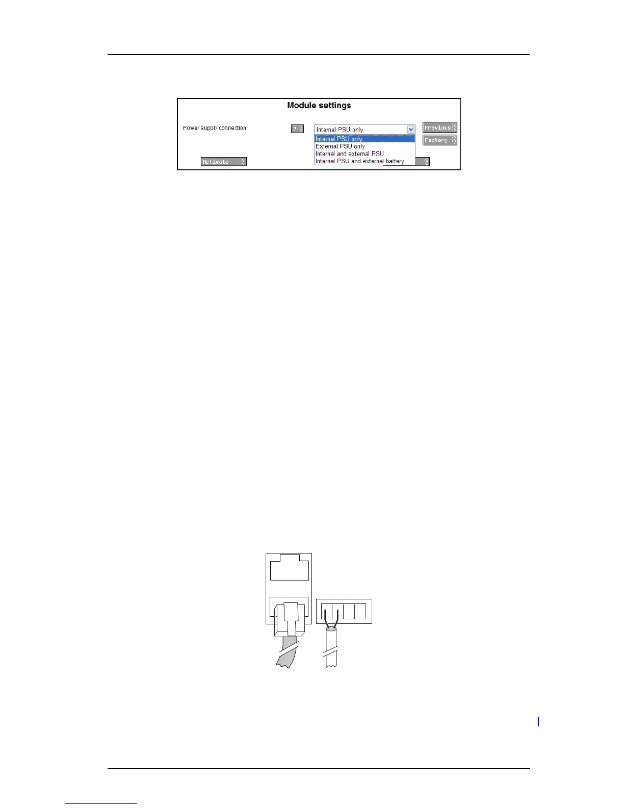
3 Select Power supply in the menu on the Advanced Configuration page.
4 Select setting in the drop-down list (Internal PSU only, External PSU only, Internal and
external PSU or Internal PSU and external battery).
5 Click “Activate”.
4.3 Connections
COM ports are available on the Elise3 Standard or LON variant. Additionally, the application
installed on the Elise3 determines if the ports can be used or not.
4.3.1 Ethernet Ports
The Elise3 has two 10baseT/100baseT Ethernet modu
lar jacks (RJ45) but only the jack
marked 1 is currently in use (the jack marked 2 is intended for future releases).
IMPORTANT: Shielded Ethernet cables should be used for installation on trains to m
eet the
regulatory requirements for railway equipment.
4.3.2 S900/A-bus connection
The Elise3 can be connected to As
com Paging System, Alarm modules, and Output modules;
either via modular system bus cabling or via twisted-pair lines to 1 and 2 on screw
connector A-bus.
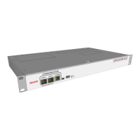
The Elise3 has two modular jacks (RJ45) marked S900 for connection of Ascom Paging
System/modules via modular bus cabling. If modular bus cabling is not used, connections
are made with twisted pairs to 1 and 2 on screw connector A-bus.
Figure 7. Modular jacks for system bus and screw connectors for twisted p
airs
4.3.3 LON Bus
NOTE: The LON connection is only availab
le on the Elise3 LON variant.