TD 92679EN
22 November 2013 / Ver. G
Installation Guide
Elise3
17
4. Installation and Configuration
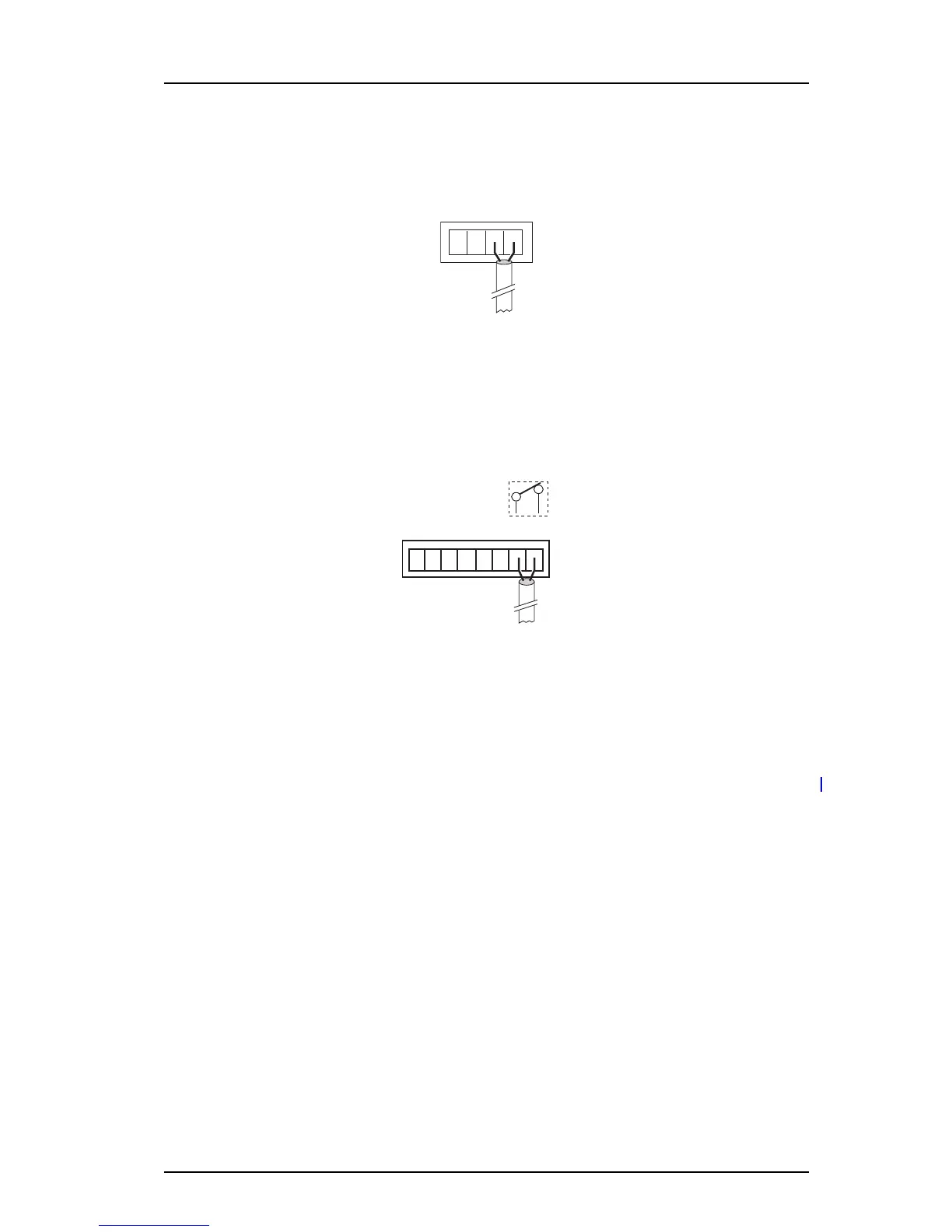
Elise3 can be connected to teleCARE M equipment. Connections are made with twisted pairs
to 1 and 2 on screw connector LON.
Figure 8. LON connector on Elise3.
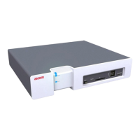
4.3.4 Error Relay Output
A relay output is used to indic
ate Elise3 malfunction and to indicate errors. Connections are
made with twisted pairs to 1 and 2 on screw connector.
Figure 9. Error relay
When the Elise3 is working properly the relay is c
losed. If the Elise3 is malfunctioning, the
relay releases to activate the error relay output. At power up or restart the relay is released
until the applications on the Elise3 are working properly.
4.3.5 AUX Connections
NOTE: The AUX connections must be supported by the s
oftware installed on the Elise3.
Two digital inputs and two digita
l outputs can be connected. The outputs are of open-
collector type and the output signals are dimensioned for 100 mA at 12 Vdc/24 Vdc.