TD 92679EN
22 November 2013 / Ver. G
Installation Guide
Elise3
18
4. Installation and Configuration
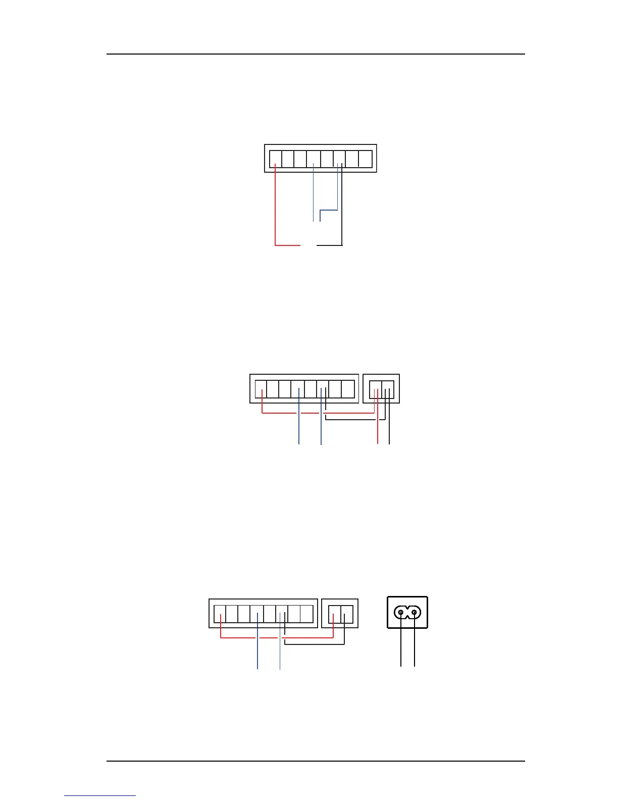
Galvanic isolation of the inputs and outputs is provided by using a separate power supply,
see figure 10.
Figure 10.
Example of AUX output with galvanic isolation.
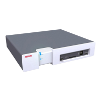
If galvanic isolation is not needed and the Elise3 is supplied by an external
12 Vdc/
24 Vdc power source, the supply voltage can be taken from the 12-24 Vdc screw
connector by connecting +V Ext to “+” and GND Ext to “-”, see figure 11.
Figure 11. Example of AUX output without galvanic isolati
on and external 12/24 Vdc
power supply/battery.
+V In In Out Out GND
Ext 1 2 1 2 Ext
External
equipment
Error
1 2
12-24 V DC 1A
+ -
Power supply
12/24 V DC
(external battery or
external PSU)
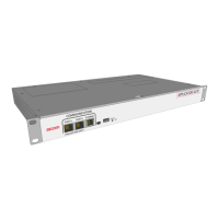
If galvanic isolation is not needed and the Elise3 is supplied by the internal
230 Vac power source, the supply voltage must also be taken from the 12-24 Vdc screw
connector by connecting +V Ext to “+” and GND Ext to “-”, see figure 12.
Figure 12. Example of AUX output without galvanic isolati
on and internal 230 Vac
power supply.