TD 92679EN
22 November 2013 / Ver. G
Installation Guide
Elise3
5
3. Description
3. Description
The Elise3 front side has different status indications and is used for maintenance. The LEDs
indicate the status of the product and the management port makes it possible to have
direct connection to the product. It also has an SD card slot and two USB ports for use with
external temporary devices.
3.1 Overview of Connectors, Buttons and LEDs
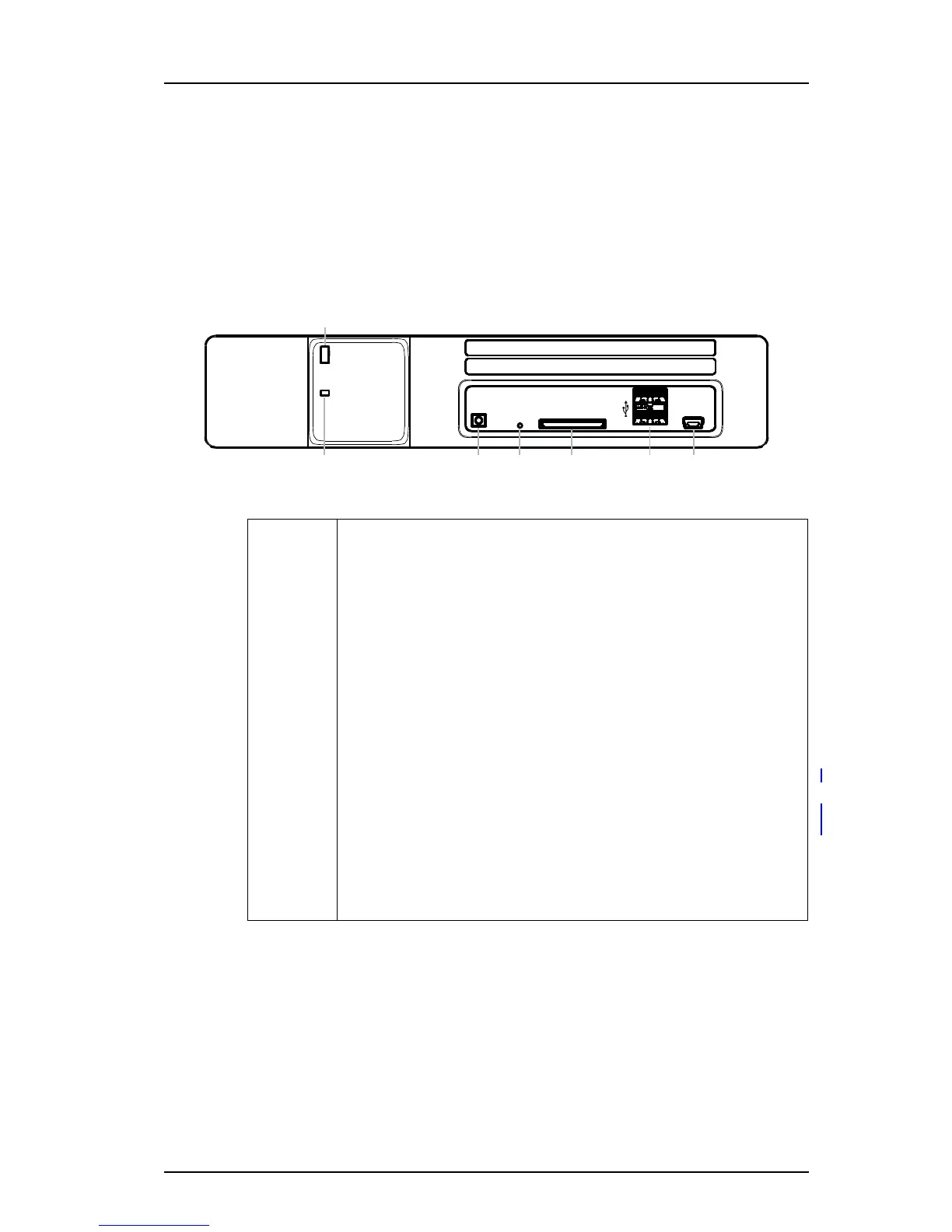
Figure 1. Front side
Front side
(a) Status LED
Indicates the product status
(b) Power LED
Indicates the power status
(c) Mode button
Used as a momentary push button with a blue LED. Used for placing the
product into specific modes by different push patterns.
(d) Restart button
A hole button that requires a paper clip (or similar) to be able to push. Used
for performing controlled restart and forced restart.
(e) SD card slot
Used as external memory for storing configuration and data. This is a
software dependent feature.
(f) USB ports
Used for upgrading of the Boot software on the field.
(g) Management
Mini-USB port for device management