INSTALLATION GUIDE
IP-DECT Base Station and IP-DECT Gateway
Installation of the Base Station
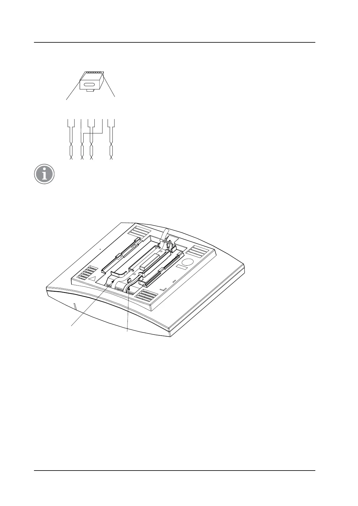
Pin the BS3x0/DB1 Cable
Figure 14. Connector pinning of the Data connector
RJ45
modular jack
EPP-b
EPP-a
SC1-a
SC0-a
SC0-b
SC1-b
NC
NC
NC
=
Not Connected
EPP
=
Express Power Pairs
SC = Serial Channel
008
1 5432 6 7 8
If local power supply is used, the EPP cable pair must NOT be connected.
3.2.8 Connect the Base Station Cables
1. Only for IPBS1: If it is required that the cables enter the base station centrally from above, guide the
cables through the recess in the middle of the base station as shown below.
Power
cable
(if used)
Data cable
016
2. Plug the modular jack of the data cable into one of the data/power connectors.
3. When an AC-adapter is used:
− Plug the modular jack of the AC-adapter in one of the data/power connectors.
− Plug the AC-adapter into a wall-outlet.
3.2.9 Mount the Base Station
Hold the base station flat against the mounting bracket and move it downwards until it clicks, see below.
TD 92989EN / 25 January 2021 / Ver. E
22