INSTALLATION GUIDE
IP-DECT Base Station and IP-DECT Gateway
Installation of the IPBL
• 110/230 VAC, 60/50 Hz
• 48 VDC
4.3.1 110/230 VAC
Only in older hardware revisions (before 5A) 110/230VAC (100 – 240 VAC) power input is
protected against overload by a 4A fuse.
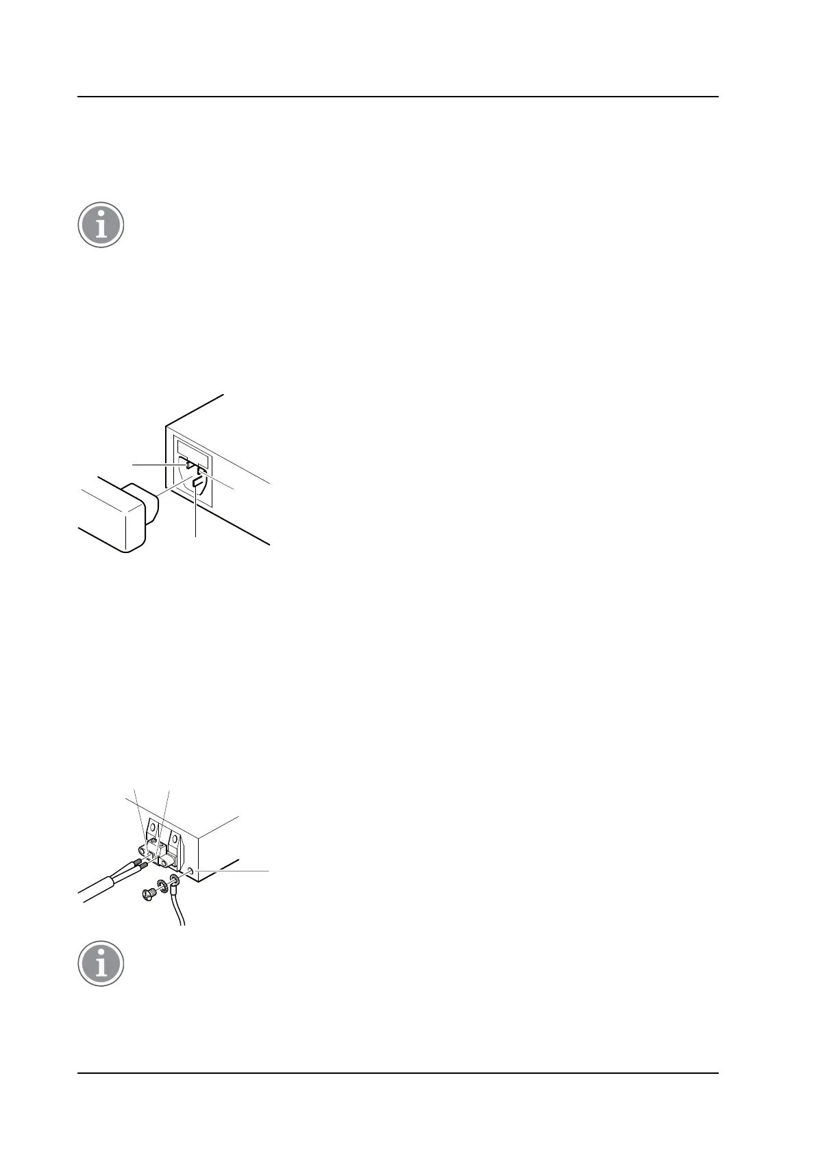
The IEC 60320 type C14 (male) connector consists of:
• live lead (1)
• neutral lead (2)
• protective earth (3)
Figure 19. Pinning of the 110/230 VAC power supply
1. Connect the power cable on the IPBL.
2. Connect the power cable in a wall socket with protected earth.
The IPBL is switched on.
4.3.2 48 VDC
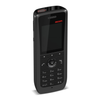
The 48 VDC (42 – 56 VDC) power input includes a fuse on the 48 VDC input to protect against overload.
The IPBL also has a protection circuit to protect both the IPBL and the external power supply from damages
caused by the user reversing the input terminals during installation.
Figure 20. Pinning of the 48 VDC power supply
A ground cable must be fastened to the protective earth (3) when 48 VDC is used as power source.
1. Fasten the ground cable to the protective earth (3) using the attached M4 screw (Philips) and washer.
2. Cut the power cable to the correct length.
TD 92989EN / 25 January 2021 / Ver. E
28