INSTALLATION GUIDE
IP-DECT Base Station and IP-DECT Gateway Description
DIP switch 1: ON
DIP switch 2: ON
1880-1900 MHz (Europe, Africa, Middle East,
Australia, New Zealand and parts of Asia)
DIP switch 1: ON
DIP switch 2: OFF
1910-1930 MHz (South America)
DIP switch 1: OFF
DIP switch 2: OFF
1920-1930 MHz (North America)
2.5.2 DB1 with External Antennas
This section contains the differences between the DB1 with internal antenna and the DB1 with external
antennas. For all other information see 2.5.1 DB1 with Internal Antenna, page 12.
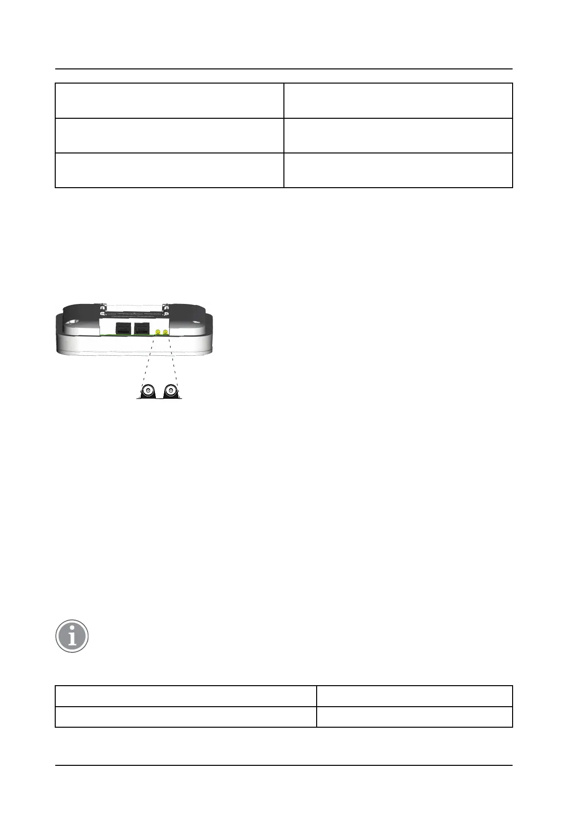
Figure 7. DB1 with MCX connectors for external antennas.
Back view while lying down
MCX connectors
Contents of the Box
The box in which the DB1 is packed contains:
• A DB1 with external antennas.
• A mounting bracket
• An antenna bracket
• Two antenna coaxial cables.
• Two antennas.
• Four screws with wall plugs
2.6 AC-adapter
The AC-adapter is used to power a base station locally.
The maximum length of cable from adapter must not exceed 10 meters.
Versions (different type of mains plug)
For European countries except UK Order. no.: BSX-0013
For UK, Australia and North America Order. no.: 660538
TD 92989EN / 25 January 2021 / Ver. E
14