INSTALLATION GUIDE
IP-DECT Base Station and IP-DECT Gateway
Installation of the IPBL
The IPBL current consumption is 0,3 A and is included in max current consumption.
For more information of power consumption of the RFPs, see Appendix A RFP Power Consumption,
page 32.
4.2 Pin the IPBL Cable
All data cables used for the IPBL is standard CAT5 unshielded cable. It is assumed that installation
personnel know how to crimp these connectors to a cable.
4.2.1 Synchronization Cable
The maximum cable length between two IPBLs must not exceed 2000 meters.
1. Cut the cable to the correct length.
2. Connect the cable to a RJ45 modular jack. For information on pinning, see Figure 17. Connector
pinning of the Sync IN cable, page 26 and Figure 18. Connector pinning of the Sync OUT cable, page
26.
3. Label the cable.
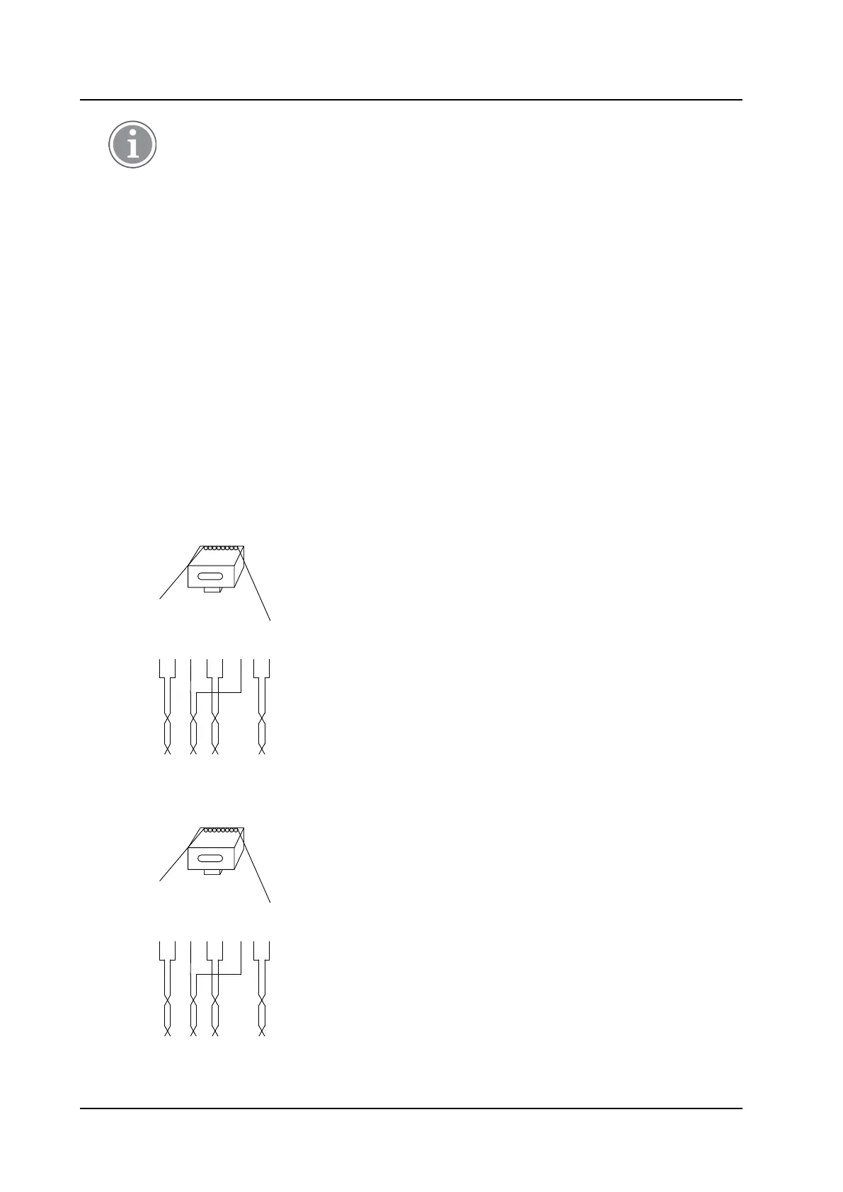
Sync IN
Figure 17. Connector pinning of the Sync IN cable
RJ45
modular jack
Sign Tx +
Sign Tx -
Sign Rx +
Rx +
Rx -
Sign Rx -
Tx +
Tx -
Sign = Signalling
Rx = Reciever data pair
Tx = Transmitter data pair
026
1 5432 6 7 8
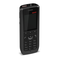
Sync OUT
Figure 18. Connector pinning of the Sync OUT cable
RJ45
modular jack
Sign Rx +
Sign Rx -
Sign Tx +
Tx +
Tx -
Sign Tx -
Rx +
Rx -
Sign = Signalling
Rx = Reciever data pair
Tx = Transmitter data pair
027
1 5432 6 7 8
TD 92989EN / 25 January 2021 / Ver. E
26