INSTALLATION GUIDE
IP-DECT Base Station and IP-DECT Gateway Description
2.5.1 DB1 with Internal Antenna
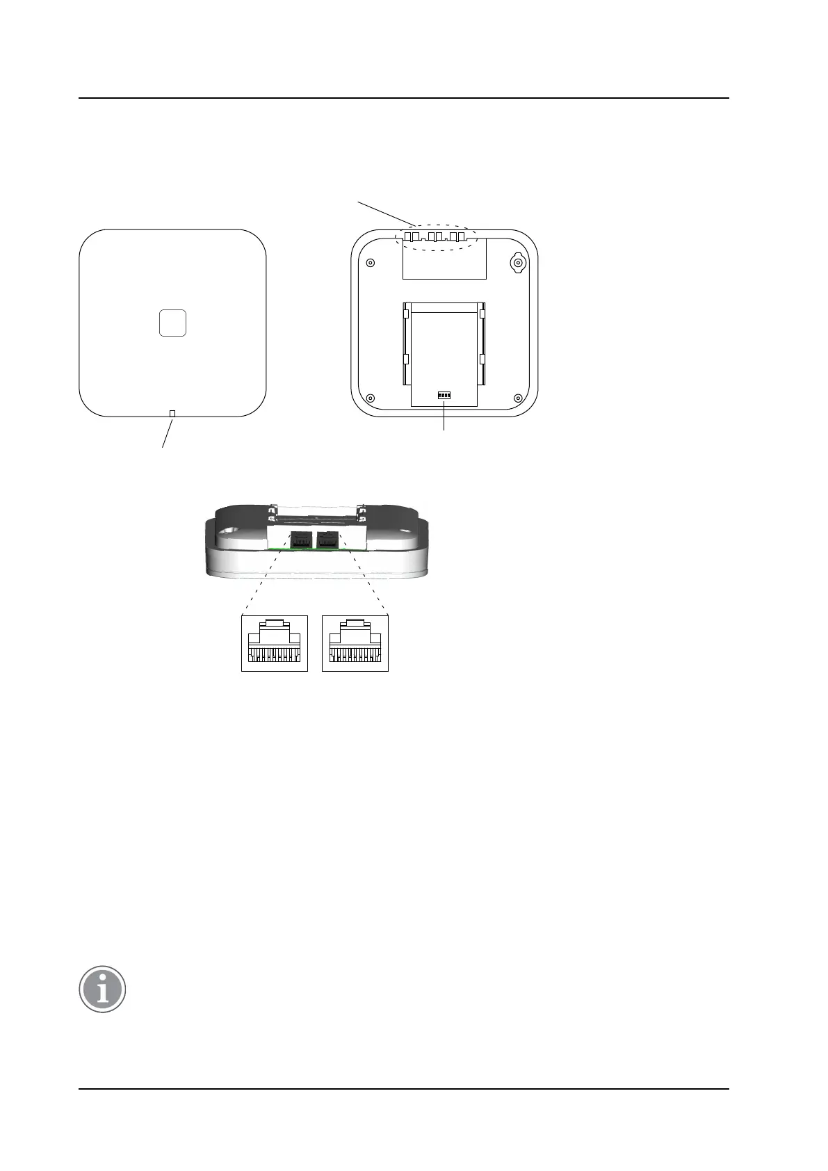
Figure 6. DB1 Overview
Front view
LED
DECT
(RJ45)
Power Supply
(RJ45)
Back view while lying down
Used for cable ties
to provide strain
relief for cables
Back view
DIP switch
1
ON
2 3 4
Contents of the Box
The box in which the DB1 is packed contains:
• A DB1 with integrated antennas
• A mounting bracket
• Two screws with wall plugs
Power Distribution
The DB1 can be powered using the following methods:
• From the IPBL via the Express Powering Pair (EPP) and data pairs
• With a local AC-adapter
For more information about power distribution, see 3.3 Power the Base Station, page 23.
TD 92989EN / 25 January 2021 / Ver. E
12