EasyManuals Logo

ascon M3 Series User Manual

ascon M3 Series
50 pages
To Next Page IconTo Next Page
To Previous Page IconTo Previous Page
Page #11 background imageLoading...
Page #11 background image
10
2 - Electrical connections
2.3 EXAMPLE OF WIRING DIAGRAM (HEAT COOL CONTROL)
B
Fuse
[5]
6
SupervisionPower supply
RS485
4…20mA
CT Current transformer 50 mA
Fuse
[5]
Power supply
switch
OP2
OP1
V
~
PTC [4]
18V
5
4
3
2
1
12
11
10
9
8
7
0P4
RX/TX
[6]
16
15
Fuse 2A~T
[6]
Allarm
V
~
OP2
18
17
14
13
OP3
[6]
V~
TC
Heating
V~
V~
Cooling
Retransmission
[3]
Notes:
1] Make sure that the power supply
voltage is the same indicated on
the instrument.
2] Switch on the power supply only
after that all the electrical con-
nections have been completed.
3] In accordance with the safety reg-
ulations, the power supply switch
shall bring the identification of the
relevant instrument. The power
supply switch shall be easily
accessible from the operator.
4] The instrument is is PTC pro-
tected. In case of failure it is sug-
gested to return the instrument to
the manufacturer for repair.
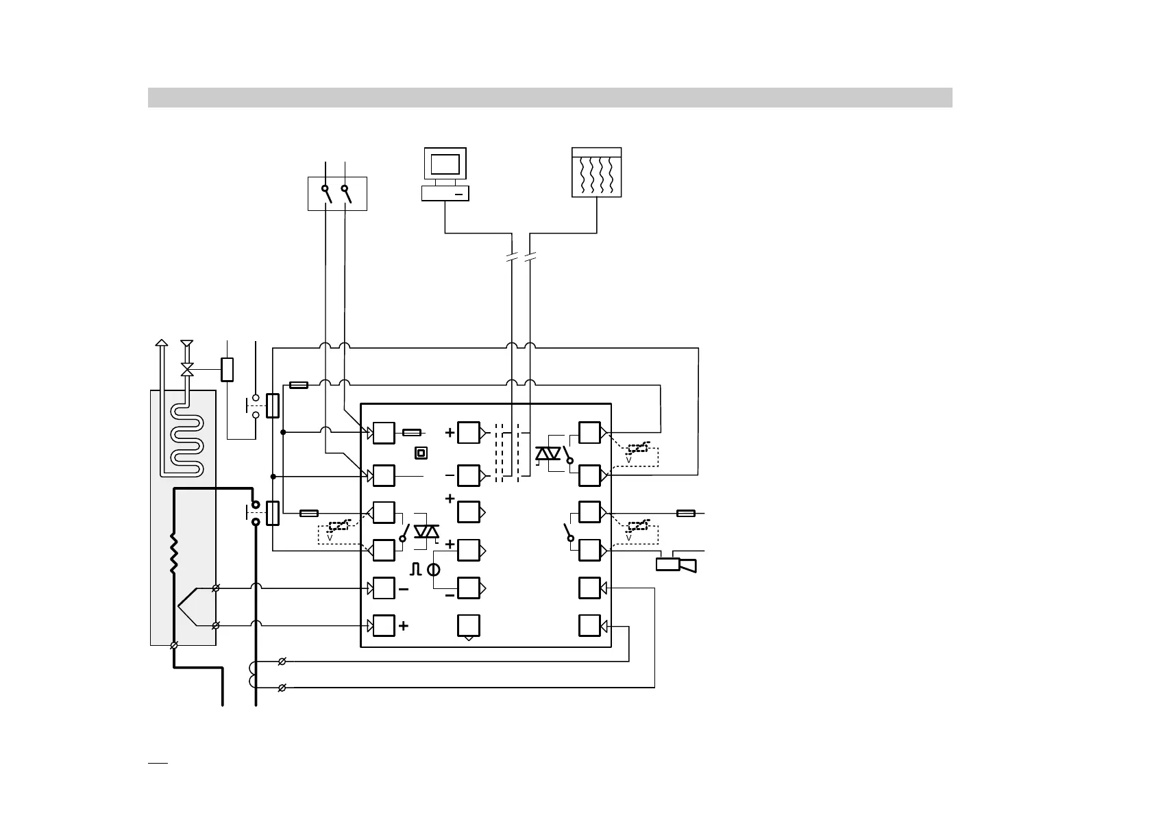
5] To protect the instrument internal
circuits use:
- 2 A
~ T fuses for Relay outputs
- 1 A
~ T fuses for Triac outputs
6] Relay contacts are already pro-
tected with varistors.
Only in case of 24 V
~ induc-
tive loads, use model A51-065-
30D7 varistors (on request)

Table of Contents

Questions and Answers:

Question and Answer IconNeed help?

Do you have a question about the ascon M3 Series and is the answer not in the manual?

ascon M3 Series Specifications

General IconGeneral
Brandascon
ModelM3 Series
CategoryTemperature Controller
LanguageEnglish

Related product manuals