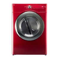
34
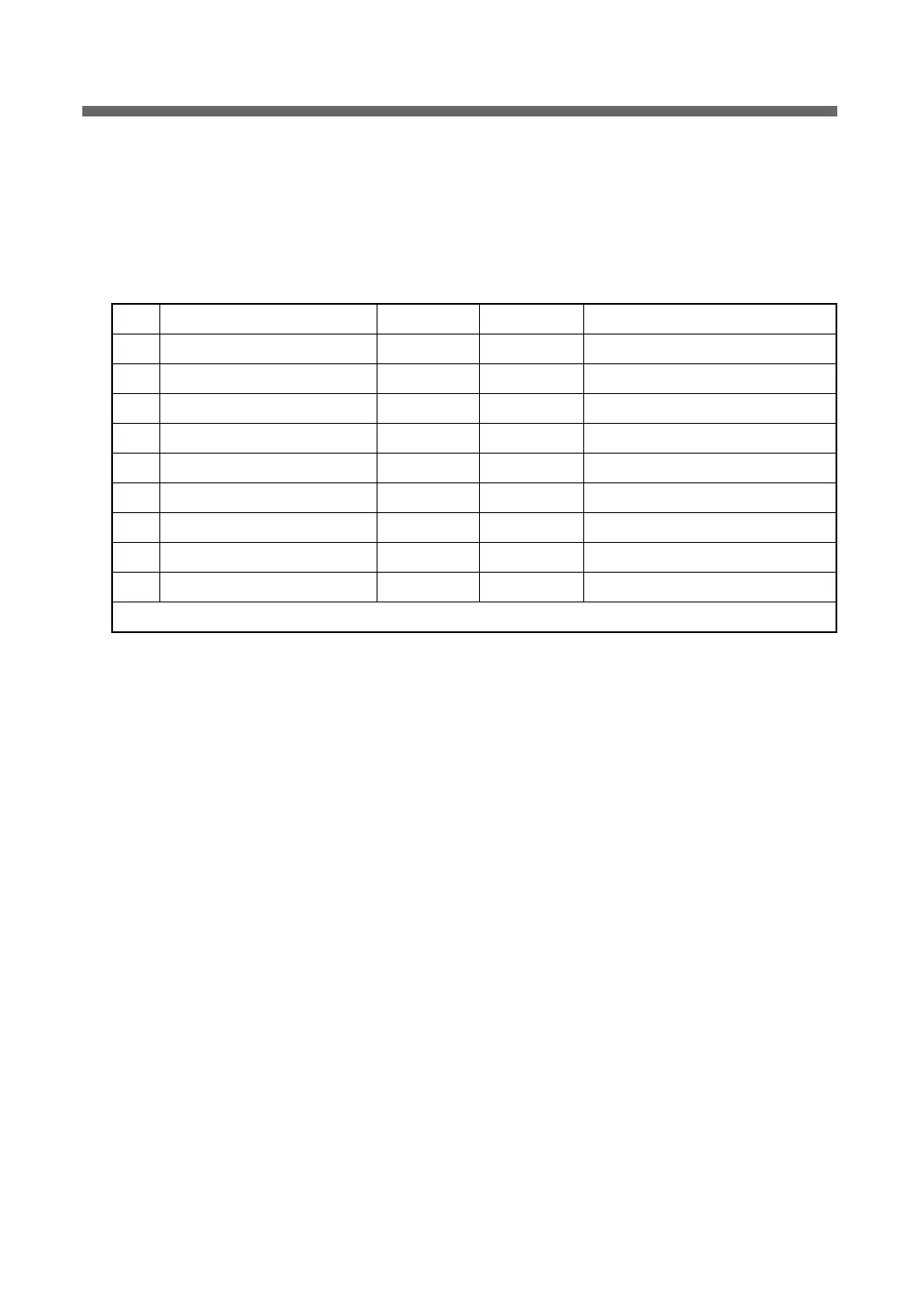
2-7. TEST Mode
1) PCB TEST MODE
A. How to enter the mode: switch the power on while pressing Dry Level and Temp Control buttons.
B. Operation order: check load by pressing Time Dry Button continually.
Fixed resistance of the temp sensor : 1.7 KΩ
No. Operation Load Time (Sec) DISPLAY Miscellaneous
1F PCB LED ALL On 0.5 ALL LED Shared by electric type and gas type.
2 Humidity sensor check 0.5 1 : xx Shared by electric type and gas type.
3 Temperature sensor check 0.5 2 : xx Shared by electric type and gas type.
4 Door S/W check 0.5 dc --> do Shared by electric type and gas type.
5 Motor check 0.5 4 : nr Shared by electric type and gas type.
6
Heater-Outer check / Ignitor check
0.5 5 : H1 Electric type / Gas type
7
Heater-Inner check / Valve 1 check
0.5 6 : H2 Electric type / Gas type
8 Valve 2 check 0.5 7 : H3 Gas type
9 Power off 0.3 Fc --> Fo Shared by electric type and gas type.
Total time 18 seconds