62
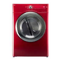
Flame Sensor
1. Function
• Sensor flame is the switch that operates by detecting fuel gas
ignition or heating of igniter.
• Contact point is opened when sufficient radiant heat is detected
through the transparent window at the bottom of sensor.
• When igniter is sufficiently heated, this is detected to turn off igniter.
Then, state of internal contact point is continuously maintained to
be off by combustion heat of the ignited gas.
• When gas supply is cut off, state of internal contact point becomes 'on' again so that to enable re-ignition
by igniter.
2. Specification
• A bi-metal switch that is operated by radiation heat
• Electric rating : 120V 5.75A
• Operation : opened within 12~20 seconds after suitable radiation starts heating it.
closed within 26~30 seconds after radiation heat disappears.
• Type name : 10RS
3. Checking method of mal-function
• At room temperature, there is the state of short between two terminals of this part.
• Part is defective if resistance between terminals measured after separating cables
connected to sensor flame is 1
Ω
or more.
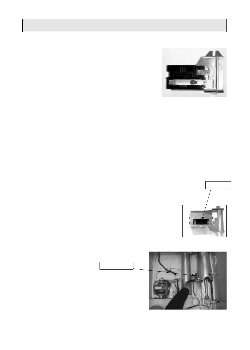
• Part is defective if the area between terminals is not opened 30 seconds after
separating sensor flame and holding flame of lighter near transparent window at the bottom
(less than 1cm).
- Flame of lighter must be as long as the length of transparent window and
the flame must not be in direct contact with transparent window.
- Transparent window of sensor flame must be kept clean at all times to
enable normal operation.
• Part is detective if resistance between terminals is not 0.3
Ω
or less within 50
seconds after removing the flame of lighter.
• In three of the above conditions, sensor flame is detective, therefore needs to be replaced.
4. Procedure of replacement
1 Remove plate top.
2 Remove panel F ass'y.
3 Remove cabinet front ass'y.
4 Remove frame upper.
5 Remove drum ass'y.
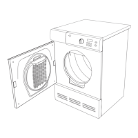
6 Check attachment position.
7 Separate the connected cable and unfasten 1 screw to
separate parts.
8 Assemble part in reverse order of the above procedures.
Part Code : 3614825700
Laniter As
Sensor Flame