RRM02 - Product Manual
Issue: 02 complete, approved
Page 13 of 68
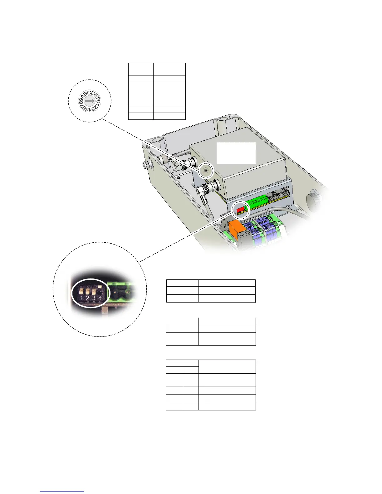
Figure 7 Radio Microphone Receiver Controls
DIP SWITCH:
1. PILOT TONE DETECTION CONFIGURATION:
2. CONFIGURATION VIA ROUTER:
3. SQUELCH LEVEL SELECTION:
(Internal wiring omitted for clarity.)
(UPPER FACE)
Switch 1 Pilot Tone Detection
Ç
Disabled
È
Enabled (default)
Switch 2 Router Configuration
Ç
Enabled (for future use)
È
Disabled (default)
Do not change.
Switches
3 4
Squelch Level
Ç Ç
Least sensitive
–76 dBm
Ç È
–86 dBm
È Ç
–93 dBm (default)
È È
Most sensitive–99 dBm
FREQUENCY SELECTION
ROTARY SWITCH
È
ON
RADIO
MICROPHONE
RECEIVER
Switch
Position
Transmitter
Channel
0 CH 01
1 CH 02
.
.
.
.
.
.
9 CH 10
A to F CH10
(Refer to Section
“5.3 Radio Microphone
Receiver Squelch Level
Configuration” (page 27)
for further details.)
(Refer to Section
“5.1Radio Microphone
Receiver Frequency
Selection” (page 34) for
further details.)
Refer to Section
“5.2 Radio Microphone
Receiver Pilot Tone
Detection Configuration”
(page 26) for further details.