RRM02 - Product Manual
Issue: 02 complete, approved
Page 14 of 68
5. Fix the RRM02 unit in its mounting position using the selected fixings and appropriate tools.
6. If antennae, or antenna cabling, are to be directly connected to the TNC connectors located on the
upper face of the unit, ensure that the internal adaptor leads are connected, and then connect the
antennae or antenna cabling in place (see Figure 8).
These leads are supplied fitted as standard. If they have been removed during the installation, then re-
connect the adaptor leads as shown in Figure 8.
See Section “3.2.2.3 Antenna Cabling” (page 10) for cabling and connector details.
L
The antennae are not supplied with the RRM02 and need to be ordered separately. The
antenna type to be used for direct connection to the RRM02 is the ASL type ANT03B.
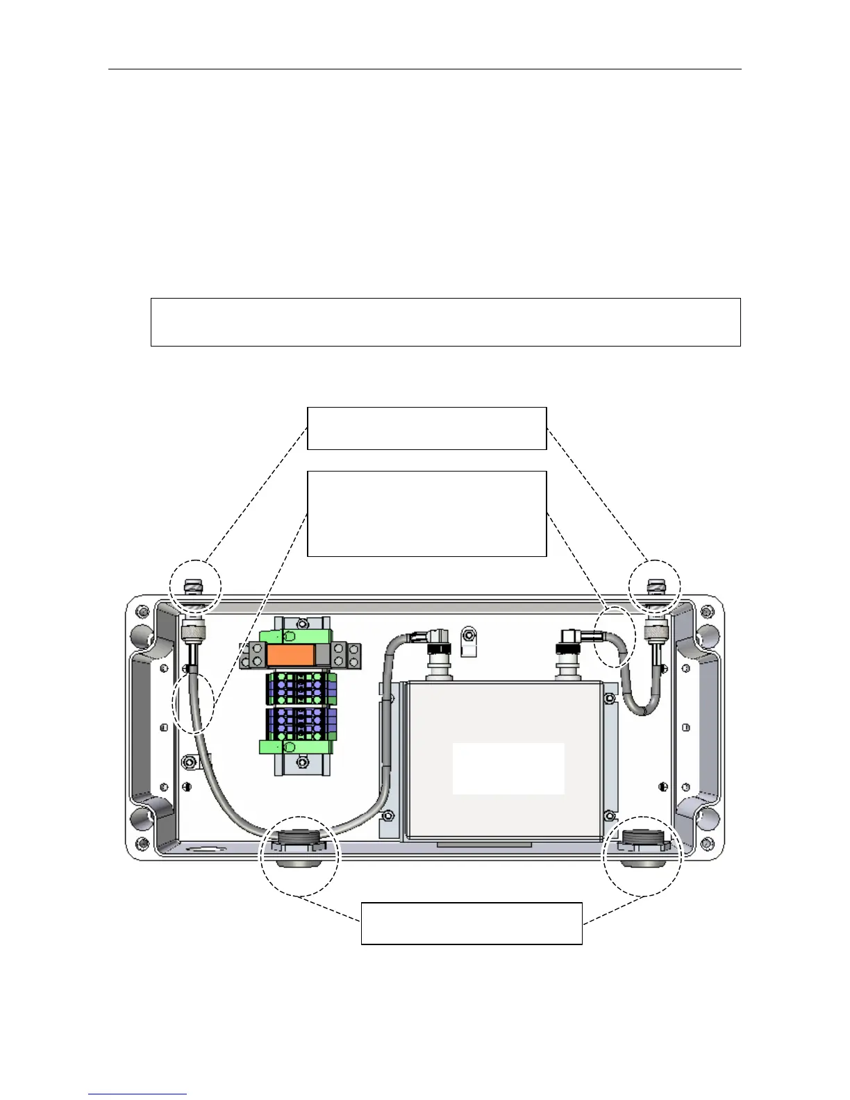
Figure 8 Internal Coaxial Lead Connection
(UPPER FACE)
(Internal wiring omitted for clarity.)
RADIO
MICROPHONE
RECEIVER
2 x ADAPTOR LEADS:
1. Long lead connected to the connectors
on the left side.
2. Short lead connected to the connectors
on the right side.
2 x ANTENNA CABLE ENTRY HOLES:
Fit tightly with blanking plugs provided.
2 x TNC CONNECTORS:
Connect antenna cable.