RRM02 - Product Manual
Issue: 02 complete, approved
Page 15 of 68
7. If antenna cables are used, and these are passed into the RRM02 through the holes provided on the
lower face of the unit, then proceed as follows.
See Section “3.2.2.3 Antenna Cabling” (page 10) for cabling and connector details. See Figure 28
(page 58) for approximate cable length inside the unit.
1. Large cables such as the RG213 or H1000 type must be connected externally to the
unit to short flexible RG58 adaptor leads due to the restricted space inside the unit.
2. The antenna cabling must not be kinked or folded at any part of the run, including
inside the RRM02 back box, or it will impair or prevent reception of the microphone
signal.
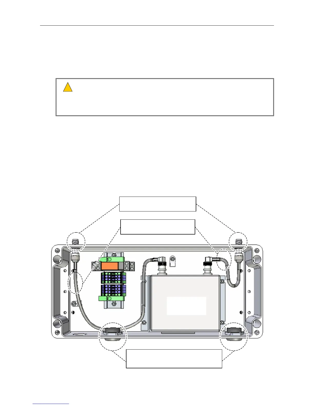
a. Remove the M25 blanking plugs on the lower face of the unit, and install the antenna cable
glands or conduits (see Figure 9).
b. Disconnect the adaptor leads connecting the TNC connectors on the upper face of the unit, if
not already done (see Figure 9).
c. Fit a blanking cap to each unused TNC connector on the upper face of the unit (see Figure 9).
Note that blanking caps are not supplied with the RRM02, and can separately be ordered from
Application Solutions (Safety and Security) Limited quoting part 207036.
Figure 9 Antenna Cabling Entry Points at Unit’s Lower Face
(UPPER FACE)
(Internal wiring omitted for clarity.)
RADIO
MICROPHONE
RECEIVER
2 x ANTENNA CABLE ENTRY HOLES (