RRM02 - Product Manual
Issue: 02 complete, approved
Page 26 of 68
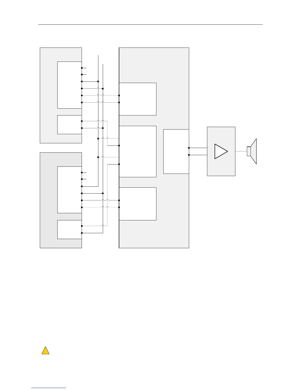
Figure 18 Connection of Two RRM02 Units on One Zone Group without Chime (Example)
ROUTER (d)RRM02
UNIT 1 (a)
PTT
RELAY
TERMINAL BLOCK
MIC INPUT 1 (a)
DXP
DXN
AUDIO+
AUDIO-
0V
+V
MIC AUDIO IN+
MIC AUDIO IN-
NO
COM
CONTACT (1)-
CONTACT (1)+
CONTACT (2)-
CONTACT (2)+
CONTACT INPUTS (e)
AUDIO OUTPUT(S) (f)
OUT (1)+
OUT (1)-
RRM02
UNIT 2 (a)
PTT
RELAY
DXP
DXN
AUDIO+
AUDIO-
0V
+V
NO
COM
MIC INPUT 2 (a)
MIC AUDIO IN+
MIC AUDIO IN-
18 - 40 V
NC (b)
NC (b)
(a) The RRM02 can be connected to any available Router inputs.
y The Router inputs are to be programmed as 'Miscellaneous Input'.
y Miscellaneous inputs used by multiple RRM02 units are to have the same priority as each other and be set to
'No Chime'.
(b) RRM02 serial data not connected to the Router.
The BUSY LED will not operate, and the ACTIVE LED will only indicate that the PTT button is being held down.
(c) VAR4/VAR12/VAR20, VAR8, and VAR8-ACU: the power supply from the Router input should not be used.
DAU or ACU: the power supply from the Router input can be used.
(d) The Router can be either a rack mounted or a wall mounted ASL PA/VA system.
y Rack mounted system: VAR4, VAR12, VAR20, VAR8, or VAR8-ACU
y Wall mounted system: DAU (Distributed Amplifier Unit), or ACU (Audio Control Unit)
Please refer to the user documentation specific to your Router for pinout details.
(e) Any available Router digital inputs can be used, connected as a simple contact closure to ground.
The contacts are to be programmed to route the relevant Router input to the required audio zone output(s).
In this example:
y Contact 1 routes Input 1 to Output 1 when the contact is closed.
y Contact 2 routes Input 2 to Output 1 when the contact is closed.
(f) Router output(s) serving the required PA zone(s). In this example, Output 1.
Cable screen tails to be connected to system ground and to be < 3 cm.
!
!
L
0 V
(c)
TERMINAL BLOCK