7
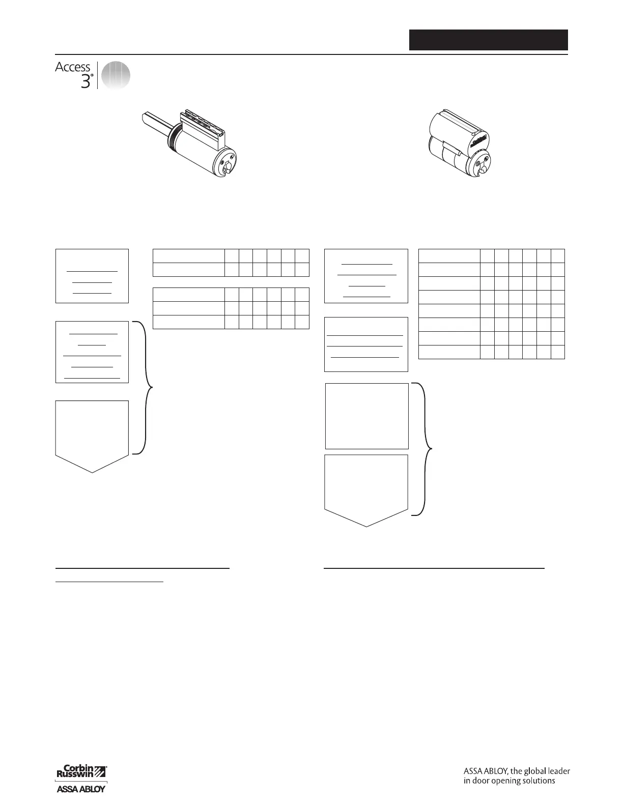
Pinning Formula
Technical Manual
Instructions (Fixed Core and LFIC
Chambers 1,2, 5 & 6)
Bottom Pin = shallowest operating cut
Master Pin (if required) = Deepest minus
shallowest operating cut
(Plug Total = Bottom Pin + Master Pin)
Top Pin = 10 MINUS Plug Total
Note: “0” depth of cut only available for AP key
systems. Not used with AS or AHS.
Fixed Core Component Cylinders
Example
Master Key 1 2 3 4 6 4
Change Key 3 4 5 2 0 2
Top Pin (TP) 7 6 5 6 4 6
Master Pin (MP) 2 2 2 2 6 2
Bottom Pin (BP) 1 2 3 2 0 2
Large Format Interchangable Core Cylinders
Example
Control Key 1 5 5 4 3 2
Master Key 1 5 2 6 3 2
Change Key 3 1 4 3 1 5
Top Pin (TP) 7 5 2 3 7 5
Build Up Pin (BU) x x 7 4 x x
Master Pin (MP) 2 4 2 3 2 3
Bottom Pin (BP) 1 1 2 3 1 2
Bottom
Pin (BP) =
Shallowest
Operating Cut
Top Pin (TP)
10 MINUS
Plug Total
Fixed Core and
LFIC Chambers
1, 2, 5 & 6
Master Pin
(MP) =
Deepest Minus
Shallowest
Operating Cut
Plug Total (MP + BP)
Instructions (LFIC Control Chambers 3 & 4)
Bottom Pin = shallowest operating cut
Master Pin (if required) = Deepest minus
shallowest operating cut
(Plug Total = Bottom Pin + Master Pin)
Build Up Pin = Control Cut plus 6 minus Plug Total
Top Pin = 13 MINUS (PLUG TOTAL + BUILD UP PIN)
Note: “0” depth of cut only available for AP key systems.
Not used with AS or AHS.
Master Pin (MP) =
Deepest MINUS
Shallowest
Operating Cut
Top Pin (TP)
13 MINUS Plug
Total and
Build Up Pin
Build Up Pin (BU) =
Control Cut PLUS 6
MINUS Plug Total
LFIC Control
Chambers 3 & 4
Bottom
Pin (BP) =
Shallowest
Operating Cut
Plug Total (MP + BP)
Lost Ball/Wafer Construction Cylinder
1. In the construction lost wafer chamber use #5 cut for TMK and #6 cut for CMK
2. CMK cuts for the rest of the chambers are same as TMK cuts
3. “Donut” wafer is added in construction lost wafer chamber above bottom pin




 To Next Page