Copyright © 2020-2021, ASSA ABLOY Inc. All rights reserved. Reproduction in whole
or in part without the express written permission of ASSA ABLOY Inc. is prohibited.
12
• The Latch can be adjusted up and down. Figures 3-5 and 3-6 show the maximum and the minimum dimensions for the
Strike location.
• Remove the Flat Head Screw (6-32) at the top of the Panic Device Assembly Handle with a
5
/
64
" Hex Tool.
• Rotate the Latch a full 360 degrees turn in the left or right direction to get the height adjustment required. Turn in the
counter clockwise direction to increase the height. Turn in the clockwise direction to decrease the height.
• Make sure that both of the holes are aligned.
• Apply Threadlocker to the screw before it is replaced.
• After the height adjustment is made, replace the Flat Head Screw (6-32).
• CAUTION: If the screw is not replaced, the latch may rotate. This may cause the Latch to disengage.
• CAUTION: Do not remove the Pan Head Machine Screw (4-40).
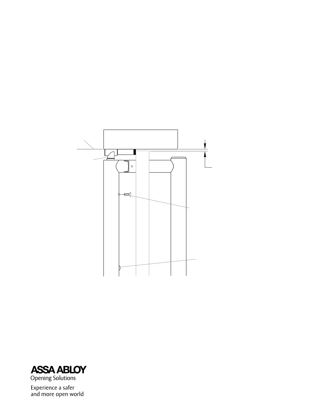
3.2 Latch Adjustment for Proper Engagement with the Strike
Figure 3-4
CAUTION
Do not Remove the Screw
Flat Head Screw (6-32)
Latch
Frame Bottom
1
/
8
" to
1
/
4
"
Ceiling
Clearance
 Loading...