*Cabinets can be configured with one or two 8 channel modules as follows; 1
High Voltage module, 1 Ground Bond Module, 2 High Voltage Modules, 2
Ground Bond Modules, or 1 High Voltage + 1 Ground Bond Module.
3.2. Instrument Controls
3.2.1. Front Panel Controls
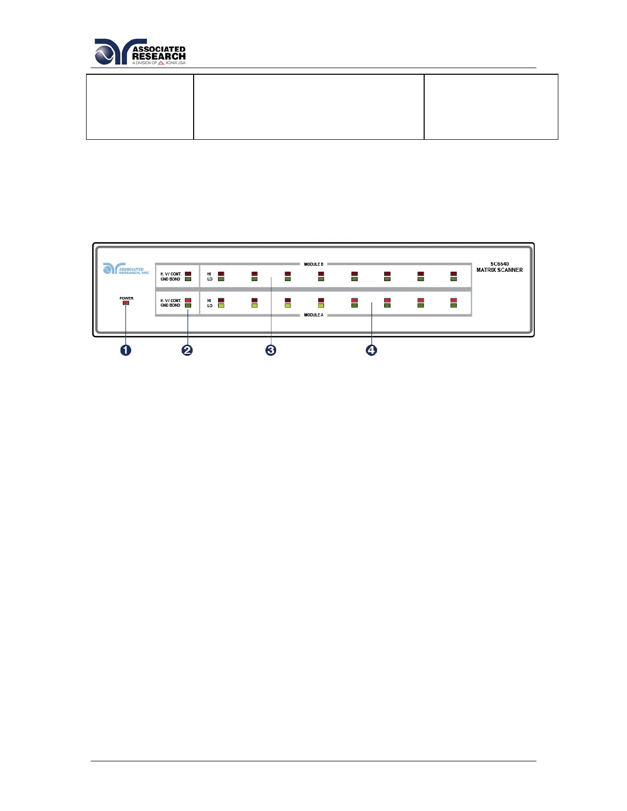
1. POWER INDICATOR: Indicates the power has been turned ON. For a
SC6540 Main, this lights when the power switch on the rear panel of the unit
is turned ON. For a SC6540 Secondary, this lights when the power switch on
the host instrument is turned ON.
2. MODULE TYPE INDICATOR: These LED’s indicate the type of module that
is installed for the corresponding module slot. If the red LED lights, it
indicates that the installed module is a High Voltage / Continuity module. If
the green LED lights, it indicates that the installed module is a Ground Bond
module.
3. MODULE B CHANNEL STATUS INDICATORS: These LED’s indicate the
status of each individual channel on Module B. If the red LED lights it
indicates a High Voltage/Continuity Current/Ground Bond Channel. If the
green LED lights it indicates a Return channel.
4. MODULE A CHANNEL STATUS INDICATORS: These LED’s indicate the
status of each individual channel on Module A. If the red LED lights it
indicates a High Voltage/Continuity Current/Ground Bond Channel. If the
green LED lights it indicates a Return channel.