4.1. Scanner Configurations
The SC6540 is available in 2 configurations according to how it sends and/or
receives data: a main and a secondary. A main Scanner can only be controlled
remotely via a PC. A secondary Scanner can be controlled locally by an
Associated Research, Inc. testing instrument or by a main Scanner.
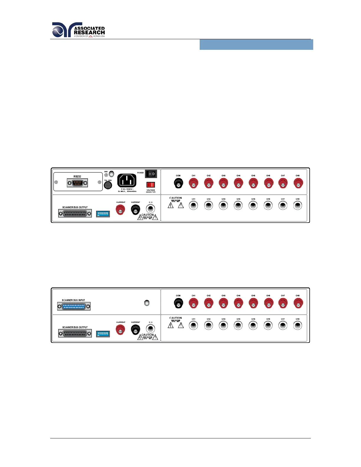
Main
A main Scanner communicates directly with a PC via a USB/RS-232 (standard),
GPIB or Ethernet interface. This model receives control information from a PC
and can also deliver instructions to up to 4 additional secondary Scanners. A main
Scanner can be distinguished by its power module located on the upper left side of
the rear panel.
Secondary
A secondary Scanner only receives data. The data that the secondary receives
can come from a main Scanner (remote control) or directly from an Associated
Research, Inc. instrument (local control). A secondary Scanner can be
distinguished by its input control bus located on the upper left side of the rear
panel.
Scanner Modules
All SC6540 Scanners are capable of supporting up to 2 Modules. Each Module
consists of either 8 HV (high voltage) ports or 8 GB (ground bond) ports. Module
A refers to a row of 8 ports of the Scanner and Module B refers to a row of 8 ports
of the Scanner (see Figure 3.0).
Scanner Models