36
Make sure the test operator is aware of the dangers of high voltage testing before
operating this equipment.
Secondary Scanner Power
Once the SC6540 secondary is connected to OMNIA, the “power on” LED will light
as soon as the power switch of the OMNIA is turned on.
Main Scanner Power
The SC6540 main is powered on by putting the switch on the rear panel of the unit
in the ON position.
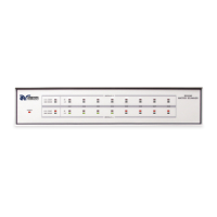
LED Indicators
The two leftmost LEDs for Module A and Module B indicate the type of module
that has been installed. If the Red LED is illuminated there is a High Voltage
module present. If the Green LED is illuminated there is a Ground Bond module
present. During a test, individual LED indicators for each output indicate whether
the output is set as High, Low or Open. If the channel is set as a High Voltage
Output, Ground Bond Output or Continuity Current Output, the red LED will light.
If the channel is set as Return, the green LED will light. If the high voltage channel
set to Open, no LED will light.
Multiple high voltage or Continuity current channels can be
set to activate simultaneously. However, when configured
this way the SC6540 cannot provide an indication of which
output detected failure. Therefore, each item or test point would again have to be
re-tested individually if the operator needs to determine the exact point of failure.
4.4. Interfacing Multiple SC6540s
The SC6540’s modular design allows the operator to interface multiple scanning
matrixes with an Associated Research automated electrical safety tester. One
SC6540 main Scanner has the ability to control up to four SC6540 secondary
Scanners.
4.4.1. Scanner Interconnection
An SC6540 main scanning matrix can be controlled by a GPIB, USB/RS232 or
Ethernet interface. Both interfaces come standard on the rear panel of the
instrument. To connect an SC6540 secondary to a SC6540 main, simply connect
the main’s Scanner Bus Output connector to the secondary’s Scanner Bus Input
connector with the 25-pin Scanner Bus Cable (p/n 38592) that is included with the
SC6540 secondary Scanner. For systems that contain more than one secondary,
connect the Scanner Bus Output connector on the first secondary to the Scanner
Bus Input connector on the second secondary with a second 25-pin Scanner Bus
Cable. This procedure should be followed with each additional secondary that is
added to the system.
The Scanner Interconnect Kit (p/n 240-01) comes complete with the following
items: