39
4.4.3. Scanner Addressing
Addressing Main Units
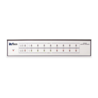
The address switches located on the rear of the Scanner must be configured in
order to ensure proper communication. The 8 pin DIP switch on the SC6540 main
should be configured to the GPIB address (if applicable) you wish to use. This will
allow the computer to communicate correctly with the main Scanner(s) connected
to the bus. The 8 pin DIP switch uses pins 1-5 to set the GPIB address. Pins 6
through 8 on the main scanner are not used. The DIP switch is set in the up
position for ON and in the down position for OFF. This is opposite to what the “ON”
position is shown on the actual DIP switch on the rear of the panel of the unit. The
DIP switch is arranged from pin 1 to pin 5 according to the following Binary Code.
PIN 1 = 1
PIN 2 = 2
PIN 3 = 4
PIN 4 = 8
PIN 5 = 16
The GPIB address number is the sum of the total binary code on the DIP switch.
The GPIB address must be selected before turning “ON” the unit.
Example: If you wish to set the address number on the main Scanner to 9, you
must turn “ON” (UP) DIP switch pins 1 and 4 and turn “OFF” (DOWN) pins 2, 3
and 5. If you wish to set the address number to 8, you must turn “ON” DIP switch
4 and turn “OFF” pins 1, 2, 3, and 5. A default address number of 9 is set at the
factory. For more information on GPIB or USB/RS232, consult section 5. Bus
Remote Interface GPIB/USB/RS232/Ethernet.
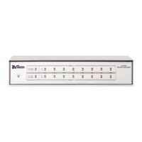
Addressing Secondary Units
Each of the SC6540 secondary units also have an 8 pin DIP address switch which
must be configured based upon the type of module installed (HV or High Current)
and the total number of points controlled by each main for each function. The first
4 switches set the address for Module A, (the lower scanner), and the last four
switches set the address for Module B, (the upper scanner) installed in each
secondary unit. The DIP switches in the secondary Scanner are arranged with the
following Binary Code for setting the circuit address (not the GPIB address):
PIN 1 = 1
PIN 2 = 2
PIN 3 = 4
PIN 4 = 8
Continued on following page…