40
PIN 5 = 1
PIN 6 = 2
PIN 7 = 4
PIN 8 = 8
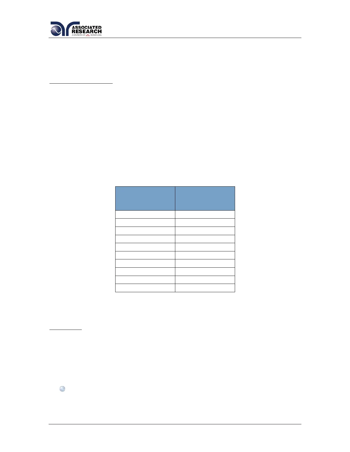
Channel Assignment
Each Scanner is capable of supporting two 8-channel modules. Each module is
physically marked on the front and rear panel with channel numbers 1 through 8.
To direct the control signals to the correct channel when using multiple scanners,
the address setting function must be used. By setting the address you are
configuring a set of virtual channel numbers for each of the modules.
Each high voltage module must have its own unique address to operate correctly.
This is also the same for each individual high current module. Since high current
and high voltage modules are for different test functions, a common address
setting can be shared between two modules of different types. The following grid
shows the set of channel numbers that are assigned for each unique address
setting.
Examples: Setting the DIP switches
Example 1: Setting up a test with either 80 HV test points or 80 High Current test
points.
The DIP switches on the main Scanner must be set to the correct GPIB address (if
applicable). A circuit address must also be assigned for each module of 8 channel
Scanners. The main scanner automatically assigns a circuit address for the two 8
channel modules installed in the main.
The circuit address will be automatically set to 0 for modules A and B if both
of the modules are of different types (1 HV and 1 High Current).