Astraada DRV-24 frequency inverters Appendix A
115
3. The drive is installed according to the instructions given in this manual.
A drive of category C3 is not intended to be used on a low-voltage
public network which supplies domestic premises. Radio frequency
interference is expected if the drive is used on such a network.
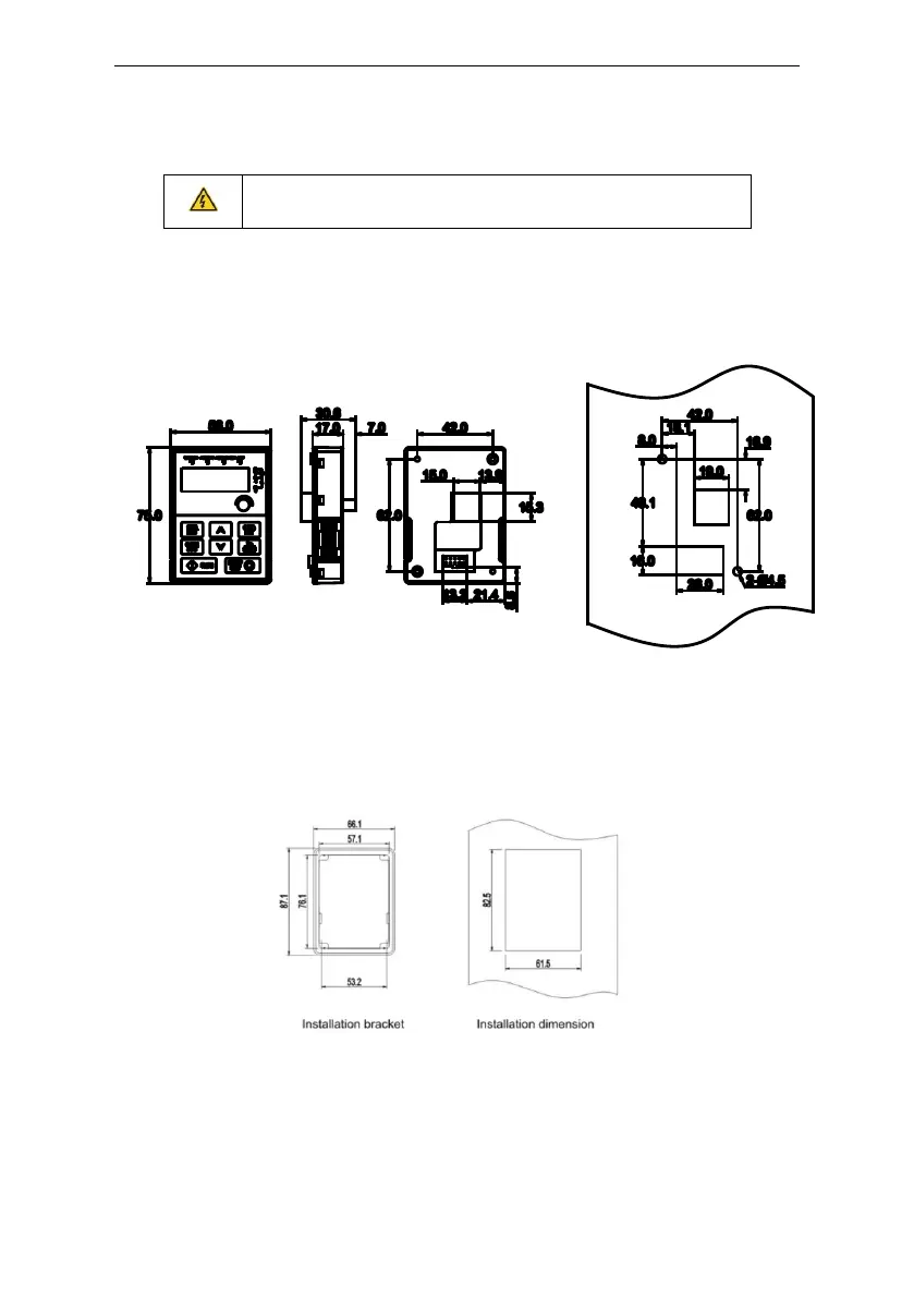
Appendix B Dimension Drawings
Dimension drawings of the Astraada DRV-24 are shown below. The dimensions are given in
millimeters and inches.
B.1 External keypad structure
Overall drawing
Hole drawing
Note: The external keypad is optional for the inverters (1PH 230V/3PH 400V ≤2.2kW); the standard
keypd of inverters (3PH 380V ≥4kW) can be used as the external keypad.
The keypad can be installed on the bracket if it is external.
 Loading...