Astraada DRV-24 frequency inverters Keypad operation procedure
24
are: set frequency, bus voltage, input terminals state, output terminals state, PID given, PID
feedback, torque set value, AI1, AI2, AI3, HDI, PLC and the current stage of multi-step speeds, pulse
counting value, length value. P07.07 can select the parameter to be displayed or not by bit and 》
/SHIFT can shift the parameters form left to right, QUICK/JOG(P07.02=2) can shift the parameters
form right to left.
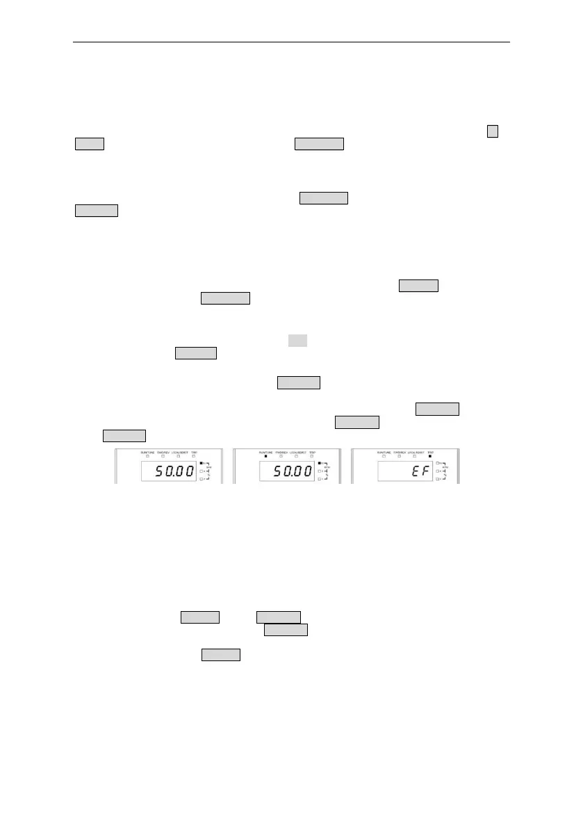
4.2.2 Displayed state of running parameters
After the inverter receives valid running commands, the inverter will enter into the running state
and the keypad will display the running parameters. RUN/TUNE LED on the keypad is on, while the
FWD/REV is determined by the current running direction which is shown as figure 4-2.
In the running state, there are 24 parameters can be selected to be displayed or not. They are:
running frequency, set frequency, bus voltage, output voltage, output torque, PID given, PID
feedback, input terminals state, output terminals state, torque set value, length value, PLC and the
current stage of multi-step speeds, pulse counting value, AI1, AI2, AI3, HDI, percentage of motor
overload, percentage of inverter overload, ramp given value, linear speed, AC input current. P07.05
and P07.06 can select the parameter to be displayed or not by bit and 》/SHIFT can shift the
parameters form left to right, QUICK/JOG(P07.02=2) can shift the parameters from right to left.
4.2.3 Displayed state of fault
If the inverter detects the fault signal, it will enter into the fault pre-alarm displaying state. The
keypad will display the fault code by flicking. The TRIP LED on the keypad is on, and the fault reset
can be operated by the STOP/RST on the keypad, control terminals or communication commands.
4.2.4 Displayed state of function codes editing
In the state of stopping, running or fault, press PRG/ESC to enter into the editing state (if there is
a password, see P07.00 ).The editing state is displayed on two classes of menu, and the order is:
function code group/function code number→function code parameter, press DATA/ENT into the
displayed state of function parameter. On this state, press DATA/ENT to save the parameters or
press PRG/ESC to escape.
Figure 4-2 Displayed state
4.3 Keypad operation
Operate the inverter via operation panel. See the detailed structure description of function codes in
the brief diagram of function codes.
4.3.1 How to modify the function codes of the inverter
The inverter has three levels menu, which are:
1. Group number of function code (first-level menu)
2. Tab of function code (second-level menu)
3. Set value of function code (third-level menu)
Remarks: Press both the PRG/ESC and the DATA/ENT can return to the second-level menu from the
third-level menu. The difference is: pressing DATA/ENT will save the set parameters into the control
panel, and then return to the second-level menu with shifting to the next function code
automatically; while pressing PRG/ESC will directly return to the second-level menu without saving
the parameters, and keep staying at the current function code.
Under the third-level menu, if the parameter has no flickering bit, it means the function code
cannot be modified. The possible reasons could be:
1) This function code is not modifiable parameter, such as actual detected parameter, operation
records and so on;
 Loading...