Astraada DRV-24 frequency inverters Installation guidelines
14
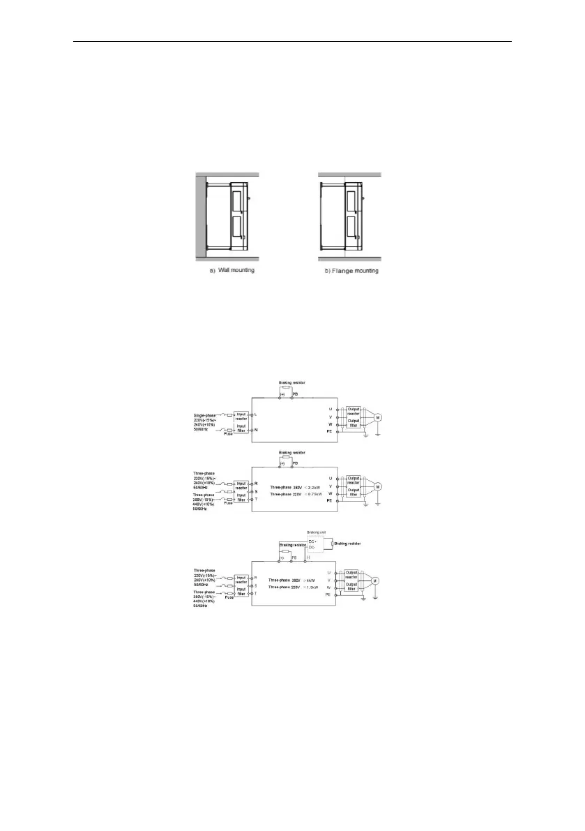
(2) Wall and flange mounting for the inverters(three phase 400V, ≥4KW)
Figure 3-2 Installation
(1) Locate the position of the installation hole.
(2) Fix the screw or nut on the located position.
(3) Put the inverter againse the wall.
(4) Tighten up the screws.
3.2 Standard wiring
3.2.1 Connection diagram of main circuit
Figure 3-3 Connection diagram of main circuit
Note:
The fuse, braking resistor, input reactor, input filter, output reactor, output filter are
optional parts. Please refer to Peripheral Optional Parts for detailed information.
Remove the yellow waring labels of PB, (+) and (-) on the terminals before connecting the
braking resistor; otherwise poor connection may be occur.
 Loading...