EasyManuals Logo

Astraada DRV-24 User Manual

Astraada DRV-24
129 pages
To Next Page IconTo Next Page
To Previous Page IconTo Previous Page
Page #17 background imageLoading...
Page #17 background image
Astraada DRV-24 frequency inverters Installation guidelines
15
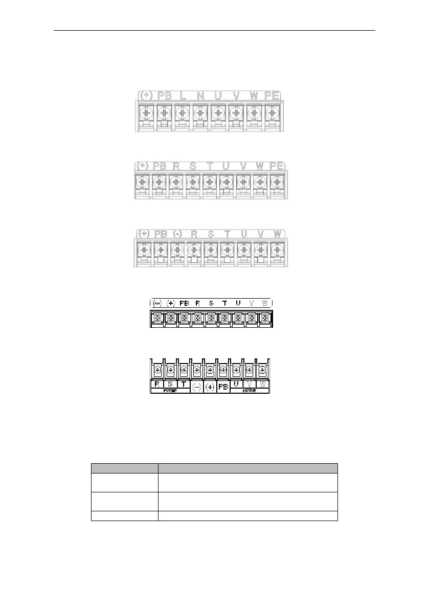
3.2.2 Terminals figure of main circuit
Figure 3-4 1PH terminals of main circuit (single phase)
Figure 3-5 3PH terminals of main circuit (400V, ≤2.2kW)
Figure 3-6 3PH terminals of main circuit (400V, 4-22kW)
Figure 3-7 3PH terminals of main circuit (30-37kW)
Figure 3-8 3PH terminals of main circuit (45-110kW)
Terminal
Function
L, N
Single phase AC input terminals which are generally
connected with the power supply.
R, S, T
Three phase AC input terminals which are generally
connected with the power supply.
PB, (+)
External dynamic braking resistor terminal

Questions and Answers:

Question and Answer IconNeed help?

Do you have a question about the Astraada DRV-24 and is the answer not in the manual?

Astraada DRV-24 Specifications

General IconGeneral
BrandAstraada
ModelDRV-24
CategoryInverter
LanguageEnglish