Note:
Do not use asymmetrically motor cables. If there is a symmetrically grounding
conductor in the motor cable in addition to the conductive shield, connect the
grounding conductor to the grounding terminal at the inverter and motor ends.
Route the motor cable, input power cable and control cables separately.
3.2.3 Wiring of terminals in main circuit
1. Fasten the grounding conductor of the input power cable with the grounding terminal of the
inverter (PE) by 360 degree grounding technique. Connect the phase conductors to L1, L2 and L3
terminals and fasten.
2. Strip the motor cable and connect the shield to the grounding terminal of the inverter by 360
degree grounding technique. Connect the phase conductors to U, V and W terminals and fasten.
3. Connect the optional brake resistor with a shielded cable to the designated position by the same
procedures in the previous step.
4. Secure the cables outside the inverter mechanically.
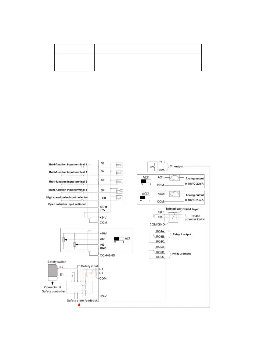
3.2.4 Wiring diagram of control circuit
Figure 3-9 Wiring of control circuit
 Loading...