Astraada DRV-24 frequency inverters Appendix C
120
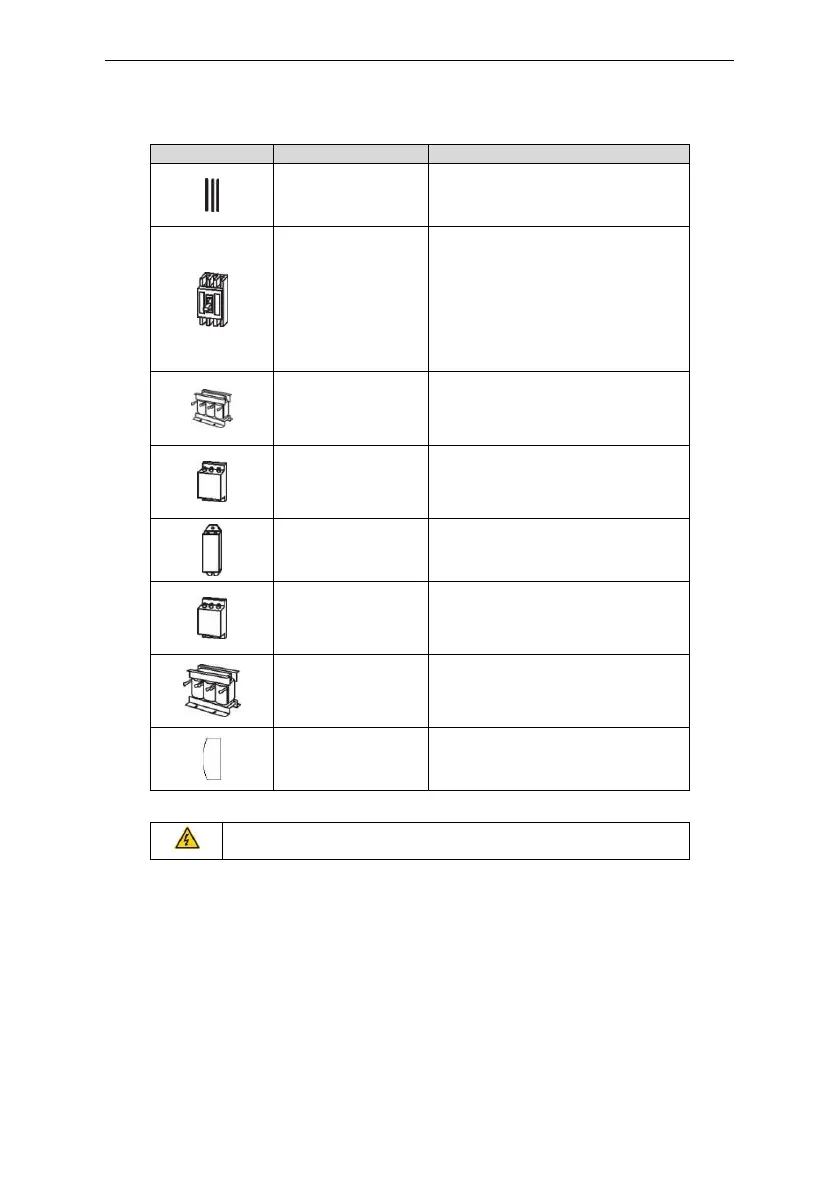
Device to transfer the electronic
signals
Prevent from electric shock and
protect the power supply and the
cables system from overcurrent when
short circuits occur. (Please select the
breaker with the function of reducing
high order harmonic and the rated
sensitive current to 1 inverter should
be above 30mA).
This device is used to improve the
power factor of the input side of the
inverter and control the higher
harmonic current.
Control the electromagnetic
interference generated from the
inverter, please install close to the
input terminal side of the inverter.
Shorten the DEC time.
Only braking resistors are needed for
Astraada DRV-24 inverters.
Control the interference from the
output side of the inverter and please
install close to the output terminals of
the inverter.
Prolong the effective transmitting
distance of the inverter to control the
sudden high voltage when switching
on/off the IGBT of the inverter.
Membrane of heat
releasing holes at the
side
Apply to severe environment and
improve protective effect.
Derate 10% of the machine.
Check that the voltage degree of the inverter complies with the
voltage of the supply power voltage.
C.3 Cables
C.3.1 Power cables
Dimension the input power and motor cables according to local regulations.
Note: A separate PE conductor is required if the conductivity of the cable shield is not sufficient for
the purpose.
C.3.2 Control cables
All analog control cables and the cable used for the frequency input must be shielded.
The relay cable needs the cable type with braided metallic screen.
Note: Run analog and digital signals in separate cables.
 Loading...