Astraada DRV-24 frequency inverters Keypad operation procedure
23
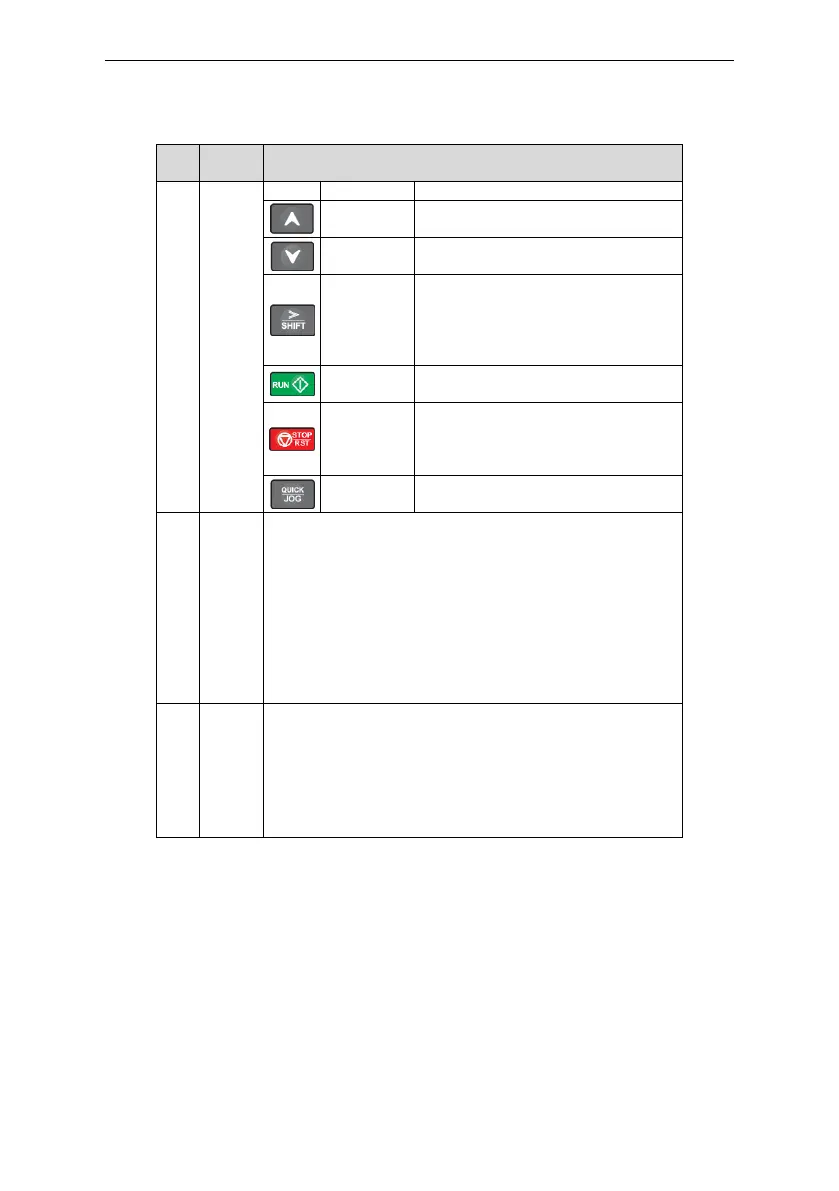
Increase data or function code
progressively
Decrease data or function code
progressively
Move right to select the displaying
parameter circularly in stopping and
running mode.
Select the parameter modifying digit
during the parameter modification
This key is used to operate on the inverter
in key operation mode
This key is used to stop in running state
and it is limited by function code P07.04
This key is used to reset all control modes
in the fault alarm state
The function of this key is confirmed by
function code P07.02.
AI1, When the external common keypad (without the function of
parameter copy ) is valid, the difference between the local keypad
AI1 and the external keypad AI1 is:
When the external keypad AI1 is set to the Min. value, the local
keypad AI1 will be valid and P17.19 will be the voltage of the local
keypad AI1; otherwise, the external keypad AI1 will be valid and
P17.19 will be the voltage of the external keypad AI1.
Note: If the external keypad AI1 is frequency reference source,
adjust the local potentiometer AI1 to 0V/0mA before starting the
inverter.
External keypad port. When the external keypad with the function
of parameter copying is valid, the local keypad LED is off; When the
external keypad without the function of parameter copying is valid,
the local and external keypad LEDs are on.
Note: Only the external keypad which has the function of
parameters copy owns the function of parameters copy, other
keypads do not have. (only for the inverters≤2.2kW)
4.2 Keypad displaying
The keypad displaying state of Astraada DRV-24 series inverters is divided into stopping state
parameter, running state parameter, function code parameter editing state and fault alarm state and
so on.
4.2.1 Displayed state of stopping parameter
When the inverter is in the stopping state, the keypad will display stopping parameters which is
shown in figure 4-2.
In the stopping state, various kinds of parameters can be displayed. Select the parameters to be
displayed or not by P07.07. See the instructions of P07.07 for the detailed definition of each bit.
In the stopping state, there are 14 stopping parameters can be selected to be displayed or not. They
 Loading...