Astraada DRV-24 frequency inverters Installation guidelines
17
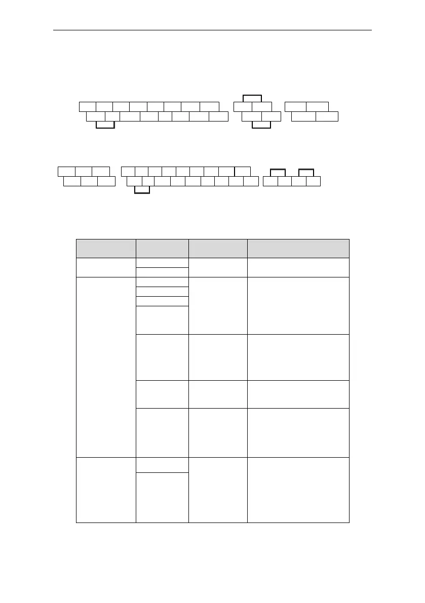
3.2.5 Terminals of control circuit
S1 S2 S3 S4 HDI AI2 AI3 +10V
+24V PW COM COM Y1 AO1 485+ 485-
+24V H1
+24V H2
RO1B RO1C
RO1A RO1C
Connection terminal diagram for inverters ≤2.2kW
S1 S2 S3 S4 HDI Y1 AI2 AI3
+24V PW COM COM GND AO1 AO2 485+
RO1A RO1B RO1C
RO2A RO2B RO2C
+10V
485- +24V H1 +24V H2
Connection
terminal diagram for inverters ≥ 4kW
Figure 3-10 Terminals of control circuit
485 communication interface
1. Internal impedance:3.3kΩ
2. 12~30V voltage input is
available
3. The terminal is the
dual-direction input terminal
4. Max. input
frequency:1kHz
High frequency
input channel
Except for S1~S4, this
terminal can be used as high
frequency input channel.
Max. inputfrequency:50kHz
Duty cycle:30%~70%
To provide the external
digital power supply
Voltage range: 12~30V
1. Contact capacity:
50mA/30V;
2. Output frequency range:
0~1kHz;
3. Default is STO state output
indicator.
External 24V±10% power
supply and the
maximum output
current is 200mA。
Generally used ad the
operation powersupply
of digital input and
output or external
 Loading...