Astraada DRV-24 frequency inverters Appendix C
126
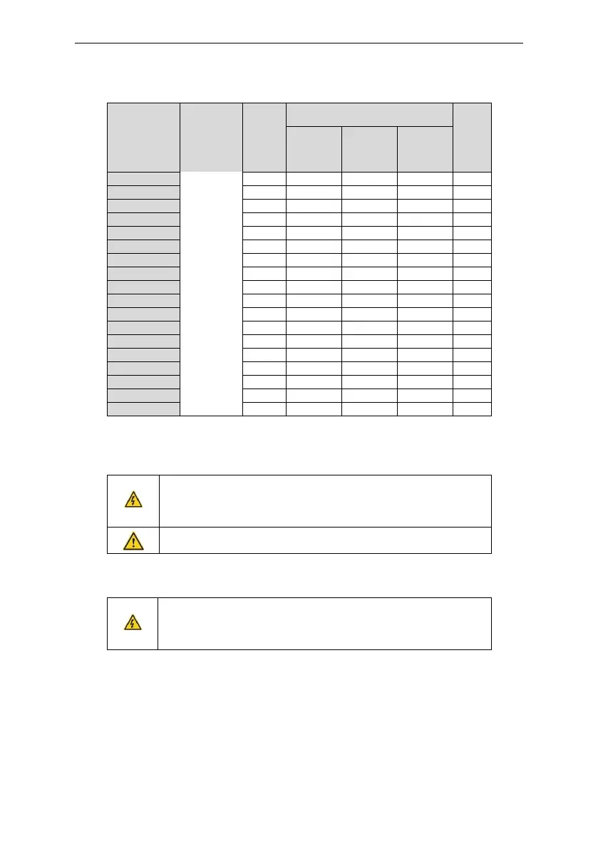
Braking
resistor at
100% of
the
braking
torque (Ω)
The consumed power of the braking
resistor
Min.
braking
resistor
(Ω)
Note:
Select the resistor and power of the braking unit according to the data our company provided.
The braking resistor may increase the braking torque of the inverter. The resistor power in the above
table is designed on 100% braking torque and 10% braking usage ratio. If the users need more
braking torque, the braking resistor can decrease properly and the power needs to be magnified.
Never use a brake resistor with a resistance below the minimum
value specified for the particular drive. The drive and the internal
chopper are not able to handle the overcurrent caused by the low
resistance.
Increase the power of the braking resistor properly in the frequent
braking situation (the frequency usage ratio is more than 10%).
C.7.2 Placing the brake resistor
Use shielded cables for braking resistor cables.
Install all resistors in a place where they will cool.
The materials near the brake resistor must be non-flammable. The
surface temperature of the resistor is high. Air flowing from the
resistor is of hundreds of degrees Celsius. Protect the resistor against
contact.
Only external braking resistor is needed in Astraada DRV-24
 Loading...