DRV-24 frequency inverters Product Overview
11
Connect the external keypad
Protect the external keypad port
Protect the internal parts and components
Hole for the sliding
cover
Protect the inner components and fix the cables
of the main circuit
See Product Overview for detailed information
Refer to the Keypad Operation Procedure
See Electric Installation for detailed information
See Electric Installation for detailed information
Fix the fan cover and fan
See Maintenance and Hardware Fault Diagnose
for detailed information
The same as the bar code on the name plate
Note: The bar code is on the middle shell which
is onder the cover
Note: In above figure, the screws at 4 and 10 are provided with packaging and
specific installation depends on the requirements of customers.
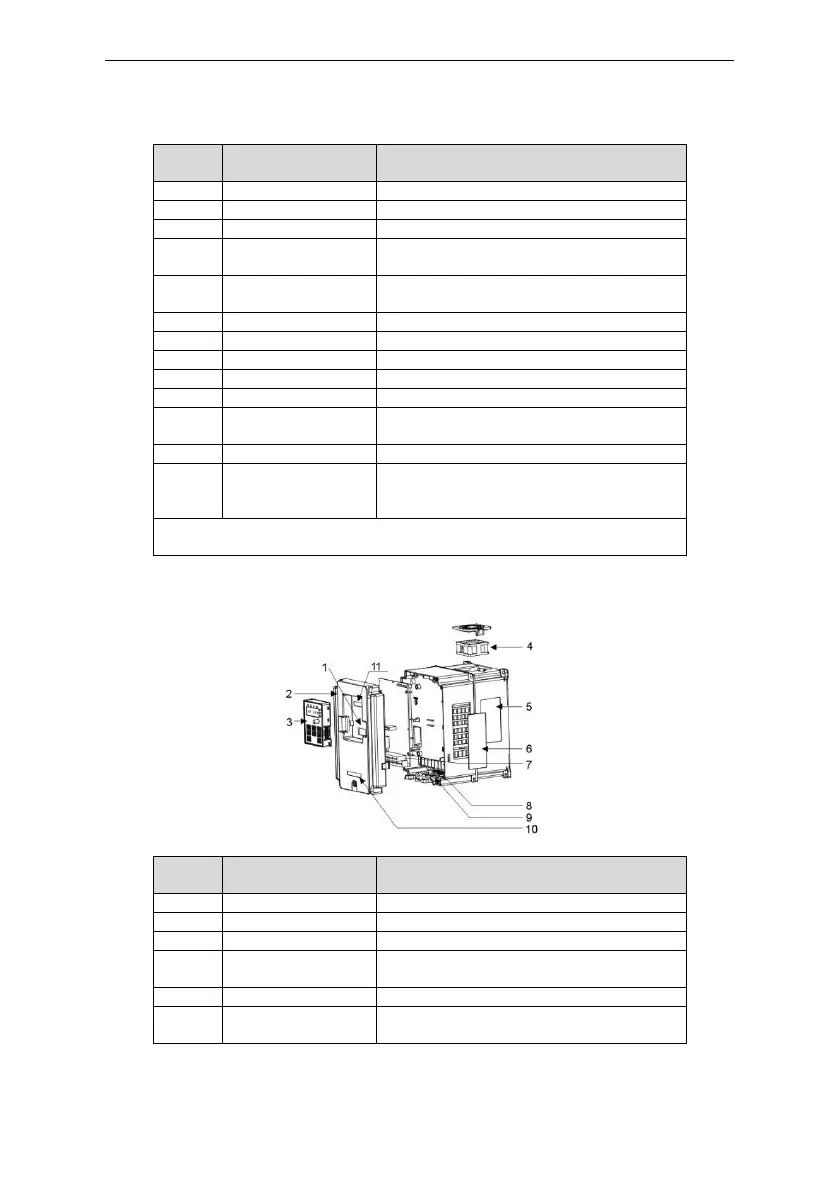
Below is the layout figure of the inverter (Three phase 400V, ≥4kW) (take the inverter of 4kW as the
example).
Figure 2-3 Product structure(Three phase 400V, ≥4kW)
Connect the external keypad
Protect the internal parts and components
Refer to the Keypad Operation Procedure
See Maintenance and Hardware Fault Diagnose
for detailed information
See Product Overview for detailed information
Cover for the heat
emission hole
Optional, enhancement of the protective degree.
It is necessary to derate the inverter because the
 Loading...