RO1 relay output, RO1A NO,
RO1B NC, RO1C common
terminal
RO2 relay output, RO2A NO,
RO2B NC, RO2C common
terminal
1. Contact capacity:
3A/AC250V, 1A/DC30V;
2. Please note that it should
not be used as high
frequency switch output;
3. *There is only RO1 relay
output for inverters ≤2.2kW.
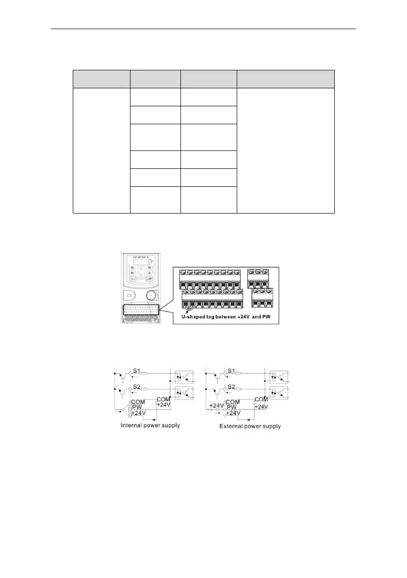
3.2.6 Input/Output signal connection figure
Please use U-shaped contact tag to set NPN mode or PNP mode and the internal or external power
supply. The default setting is NPN internal mode.
Figure 3-11 U-shaped contact tag
If the signal is from NPN transistor, please set the U-shaped contact tag between +24V and PW as
below according to the used power supply.
Figure 3-12 NPN modes
If the signal is from PNP transistor, please set the U-shaped contact tag as below according to the
used power supply.
 Loading...